This is a detailed post! We’re about to dive into the core steps of configuring our two-node cluster. But first, let’s recap where we are:
- Installed ESXi
- Deployed vCenter Server Appliance on the first node in the cluster
- Deployed the vSAN Witness
In this post, we’ll be covering a lot of ground. We’ll configure networking using a Virtual Distributed Switch (vDS), add the second host to the cluster, and integrate the vSAN Witness with vCenter. From there, we’ll create the 2-node vSAN ESA stretched cluster and resolve any alerts. This will lead us into setting up vLCM with Images, patching, and remediating the hosts. Finally, we’ll move on to post-cluster configuration, including setting up Distributed Resource Scheduler (DRS), High Availability (HA), and installing our licences.
If you haven’t already, I highly recommend reading my post on deploying the vSAN Witness. The introduction covers essential background on what a two-node cluster is, key terminology, and other prerequisite information relevant to this post.
Before we begin the configuration, I’ll walk through the logical and physical topology.
- Networking
- Adding additional Host and Witness
- Distributed Resource Scheduler (DRS)
- High Availability (HA)
- Licencing
- Summary
Networking
Physical Network
My Dell Precision 5820 hosts I am using for my GPU Homelab, I have the following network cards and connectivity.
- One onboard 1 Gbps NIC (vmnic0 – NIC1)
- One Gigabit Cable Matters USB to Ethernet Adapter (vusb0 – NIC2) – How to Add USB NIC to ESXi: Step-by-Step Guide
- In duel port 10 Gbps Mellanox ConnectX-4 PCIe card (vmnic1 – NIC 3 & vmnic2 – NIC 4) – Upgrading Mellanox ConnectX-4 Lx Firmware on ESXi: A Step-by-Step Guide
Below depicts the physical connectivity
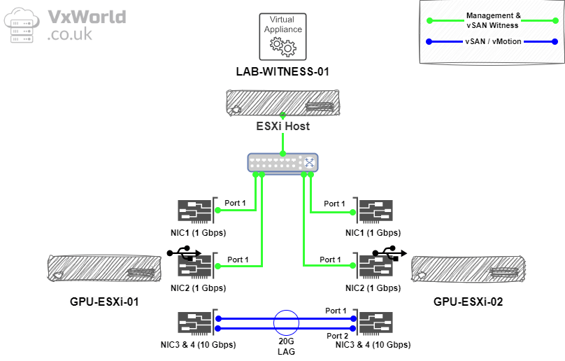
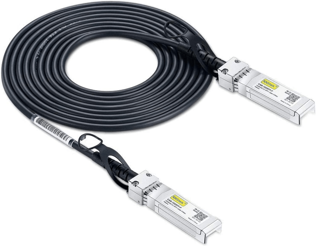
To direct connect the host, I used a pair of 10Gtek DAC cables. They worked great with the Mellanox ConnectX-4 PCIe cards once I upgraded the firmware on the NICs.
Prior to following the steps below to create a Distributed Virtual Switch, ensure you have the network cards operational.
Logical Overview
As a reminder from the vSAN Witness deployment post, the vSAN Witness traffic will traverse the management network, while the vSAN data traffic will flow over the direct links.
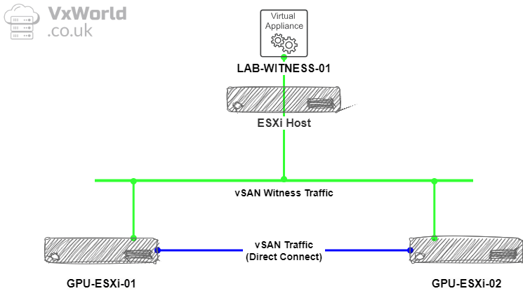
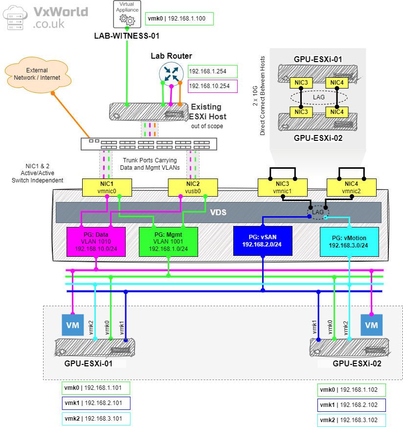
Lets break that down some more, below is the logical representation of the networking for my VMware GPU Homelab. I will be using a single Distributed Virtual Switch with four Port Groups: Management, Data, vSAN and vMotion.
I have four physical NICs to work with, the two Gigabit ones will be used for Management and Data whilst the 10Gbps NICs will be used for vSAN and vMotion.
The two 10Gbps NICs will be Direct Connected and configured in an LACP bond to get the most bandwidth out of them for vSAN and vMotion.
Create Virtual Distributed Switch
Right, let’s get stuck into the configuration! First up, we’ll create the Virtual Distributed Switch.
- Browse to the vSphere Client
- Browse to, Inventory -> Networking View -> [vCenter Server] -> [Datacentre]
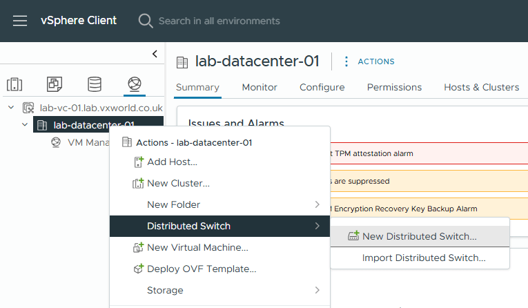
- Right Click on the [Datacentre] -> Distributed Switch -> New Distributed Switch
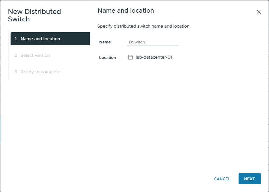
- Enter a Name for the switch. In my example, I am using the default but if for example you were going to create two, one for vSAN and one for other traffic you could name them acordanly
- Click Next
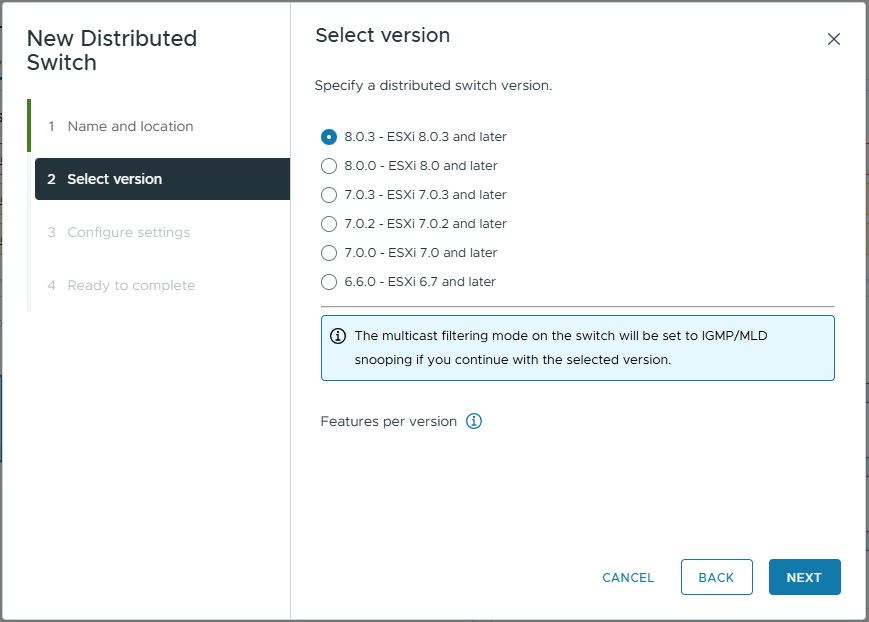
- Select the version you want. In my example, as all host are running ESXi 8.0.3, I will select that to give me all the latest features. If you have one or more hosts with a lower version, you need to select the lowest version in use within your cluster.
- Distributed switch: 8.0.3: Dual DPU Support
- Distributed switch: 8.0.0: Network Offloads Support
- Distributed switch: 7.0.3: NVMe over TCP
- Distributed switch: 7.0.2: LACP Fast Mode
- Distributed switch: 7.0.0: NSX Distributed Port Group
- Distributed switch: 6.6.0: MAC Learning
- Click Next
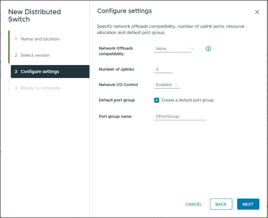
- On the configure setting, set the following
- Network Offload Compatibility: None.
In my example, I do not have any DPUs within my hosts, however If you do, you can select NVIDIA Bluefield or AMD Pensando. - Number of uplinks: 2
This is the number of physical uplinks you want to be able to connect to your distributed virtual switch (excluding ones added to LAGs) - Network I/O Control: Enabled
NIOC allows vSphere to manage contention on the physical network links - Default port group: Unchecked
In my example, I will create port groups later
- Network Offload Compatibility: None.
- Click Next
- Review your selections
- Click Finish
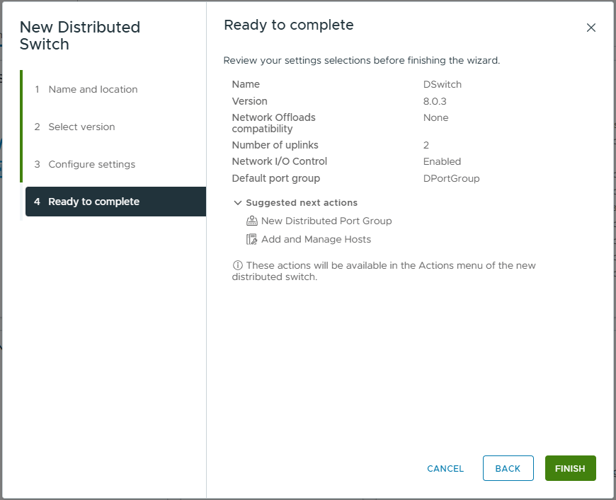
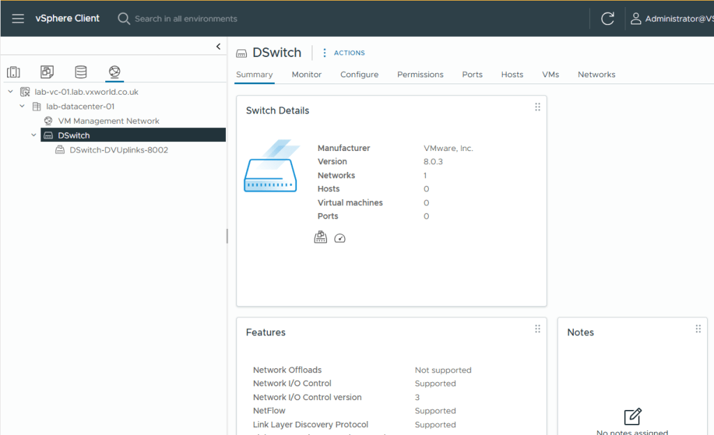
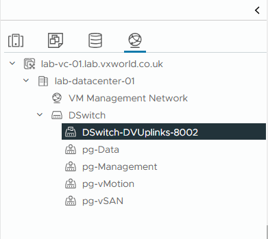
- You should now see the newly created DVS within the inventory.
- First, we are going to configure the switch to support jumbo (9000 MTU) packets.
- Select the DSwitch
- Click Actions -> Settings -> Edit Settings
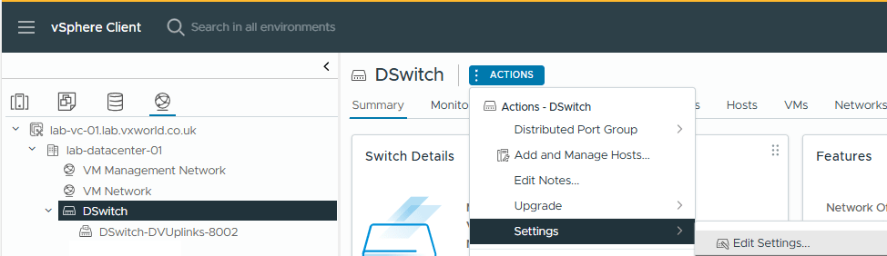
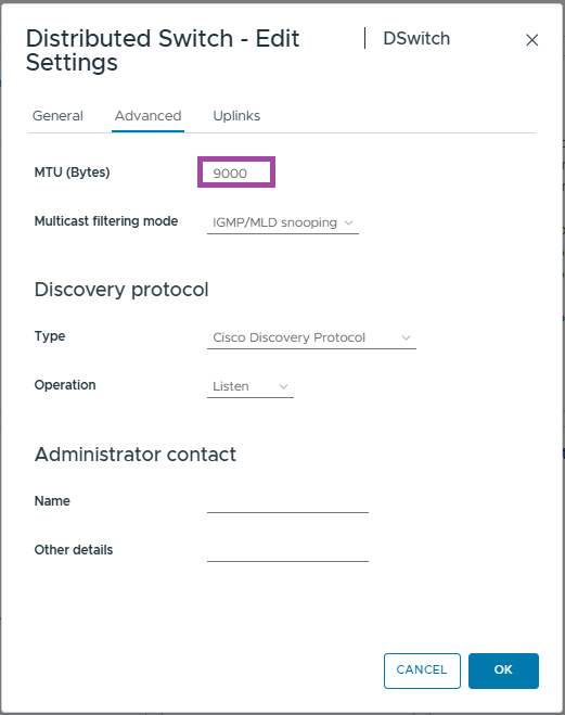
- Brose to, Advanced
- Change the MTU value from 1500 to 9000
- Click OK
- Next we are going to configure the LAGs
Creating the LAG for vSAN / vMotion
As mentioned at the start of the article, the two hosts are going to be directly connected by two 10Gbps cables. To allow us to take advantage of the bandwidth, we are going to create a Link Aggregation Group (LAG) containing two uplinks, providing 20Gbps of throughput. This LAG will be shared between vSAN and vMotion as per the diagram at the start of this post.
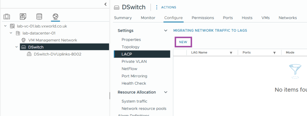
- Select the newly create vDS. In my exmaple, DSwitch
- Browse to, Configure -> Settings -> LACP
- Click New
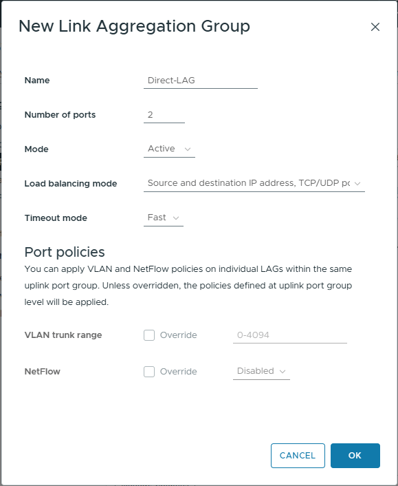
- Enter the follwong details
- Name: Direct-LAG
Enter a name of your choose. In my example, this LAG is between the two hosts, therefor the name Direct-LAG makes sense to me. - Number of ports: 2
I will only be using two uplinks between the hosts. Increase as necessary for your deployment. - Mode: Active
If this was connecting to the a switch, I would set the switch as active and the vSphere LAG as passive. The active end sends the LACPDUs to whilst the passive end waits – these are used to form the link bond. As the LAG configuration is the same for both hosts, if it was set to passive they would both wait for LACPDUs that neither host were sending and the bond would not form. This is why I have selected Active - Load balancing mode: Source and destination IP address, TCP/UDP port and VLAN
This is the default and fine for our use case - Timeout mode: Fast
In slow, the heartbeat interval is every 30 seconds. When set to fast, that is reduced to 1 second. If the heartbeat is not received after three intervals, then the link will be removed from the LAG
- Name: Direct-LAG
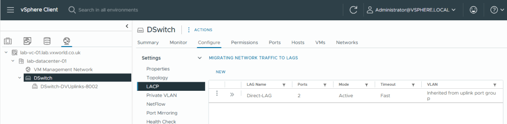
- Click OK
- You should now see the LAG you created
Create The Port Groups
The next step is to create Port Groups, which VM NICs and VMkernel interfaces connect to. These allow you to assign VLANs, map physical network cards, configure load balancing, and other various other settings. We are going to create the following Port Groups:
- pg-vSAN
- pg-vMotion
- pg-Management
- pg-Data
vSAN Port Group
Lets create the port group for vSAN.
- Right Click on the vDS
- Click Distributed Port Group -> New Distributed Port Group
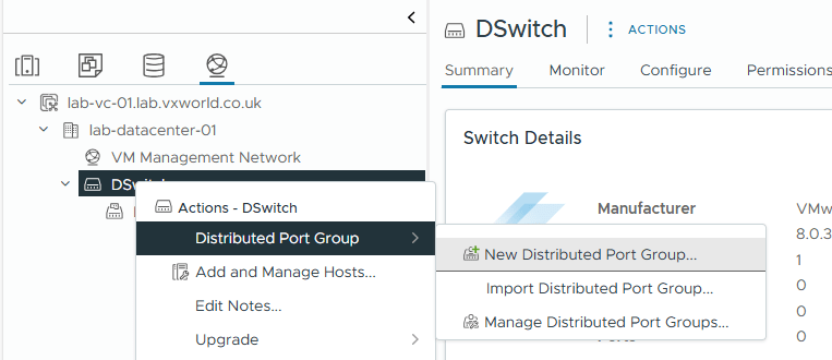
- On Name and Location, enter a Name: pg-vSAN
- Click Next

- On Configure settings, use the default settings except
- VLAN Type: VLAN
- VLAN ID: 1002 (or whatever VLAN ID you are using)
- Customized default polices configuration: Checked
- Click Next

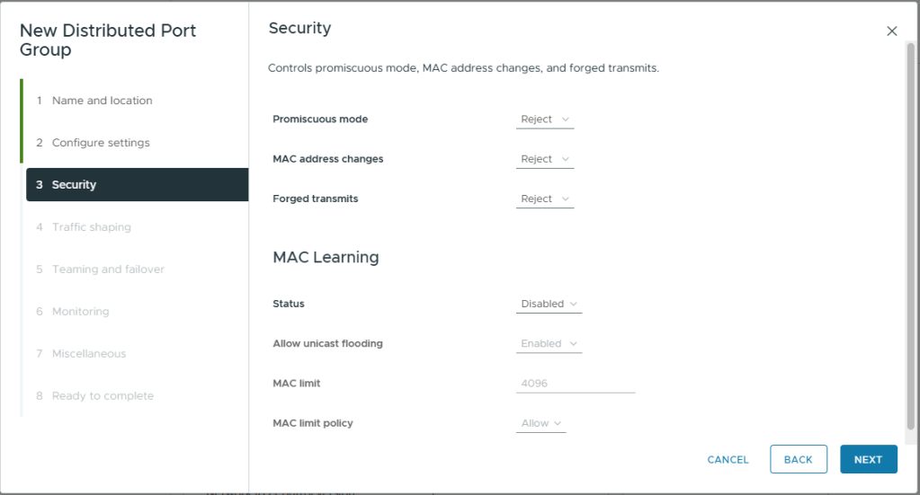
- On Security, use the default settings
- Click Next
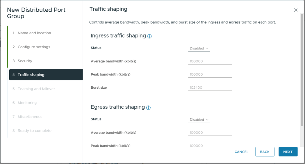
- On Traffic Shaping, use the default settings
- Click Next
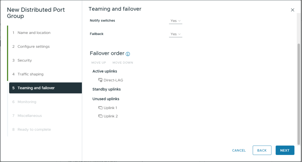
- On Teaming and failover, use the default settings except
- Move the Direct-LAG created eelier into Active uplinks
- Move all other Uplinks (1 to 4) into Unused uplinks
- Click Next
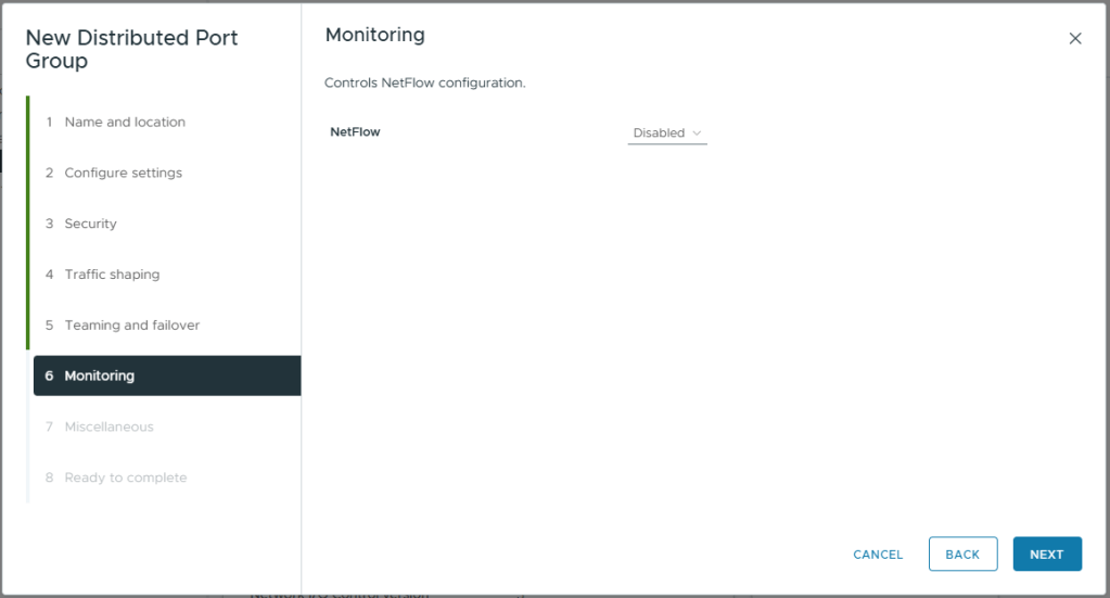
- On Monitoing, use the default settings
- Click Next
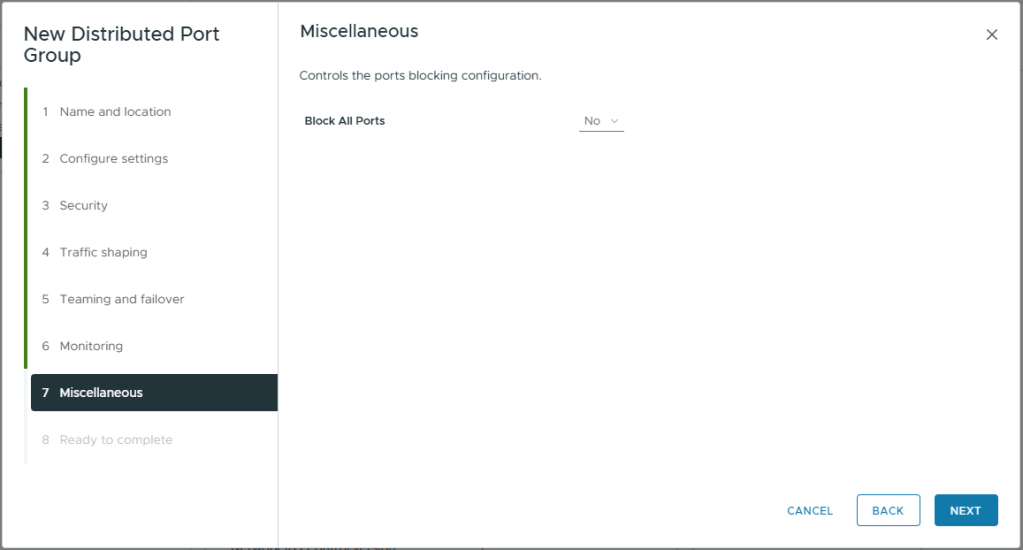
- On Miscellaneous, use the default settings
- Click Next
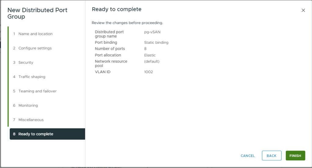
- Review your selections
- Click Finish
- You will see the newly created port group listed

vMotion Port Group
We will follow the same steps as we did for creating the vSAN port group to create the port group for vMotion, just using a different VLAN.
- Right Click on the vDS
- Click Distributed Port Group -> New Distributed Port Group
- On Name and Location, enter a Name: pg-vMotion
- Click Next

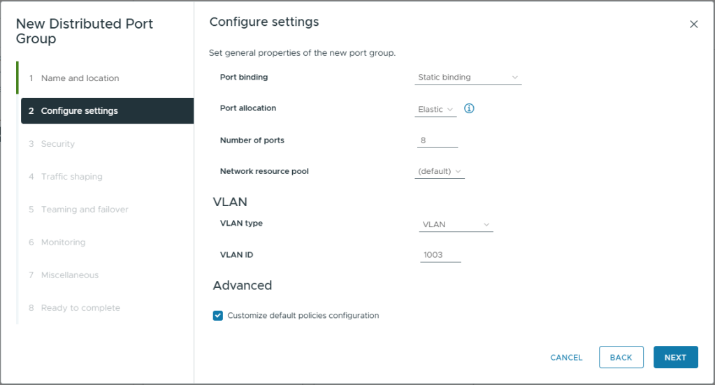
- On Configure settings, use the default settings except
- VLAN Type: VLAN
- VLAN ID: 1003 (or whatever VLAN ID you are using)
- Customized default polices configuration: Checked
- Click Next
- On Security, use the default settings
- Click Next
- On Traffic Shaping, use the default settings
- Click Next
- On Teaming and failover, use the default settings except
- Move the Direct-LAG created eelier into Active uplinks
- Move all other Uplinks (1 to 4) into Unused uplinks
- Click Next
- On Monitoring, use the default settings
- Click Next
- On Miscellaneous, use the default settings
- Click Next
- Review your selections
- Click Finish

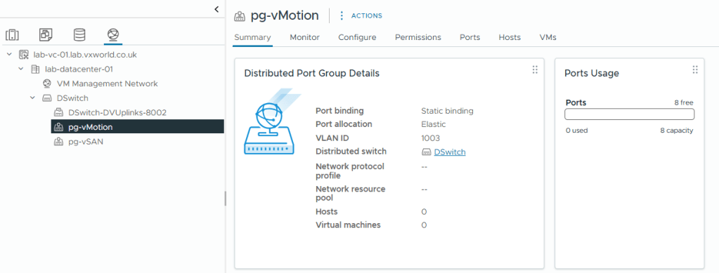
- You will see the newly created port group listed
Create the Management Port Group
Next we will create the Management port group. This process will be slightly different as we will not be using the LAG but multiple active 1GBps NICs that we will load balance using a VMware native load balancing method.
- Right Click on the vDS
- Click Distributed Port Group -> New Distributed Port Group
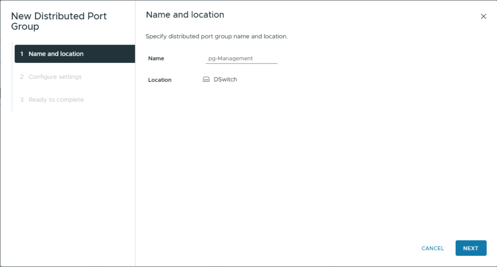
- On Name and Location, enter a Name: pg-Management
- Click Next
- On Configure settings, use the default settings except
- VLAN Type: VLAN
- VLAN ID: 1001 (or whatever VLAN ID you are using)
- Customized default polices configuration: Checked
- Click Next

- On Security, use the default settings
- Click Next
- On Traffic Shaping, use the default settings
- Click Next
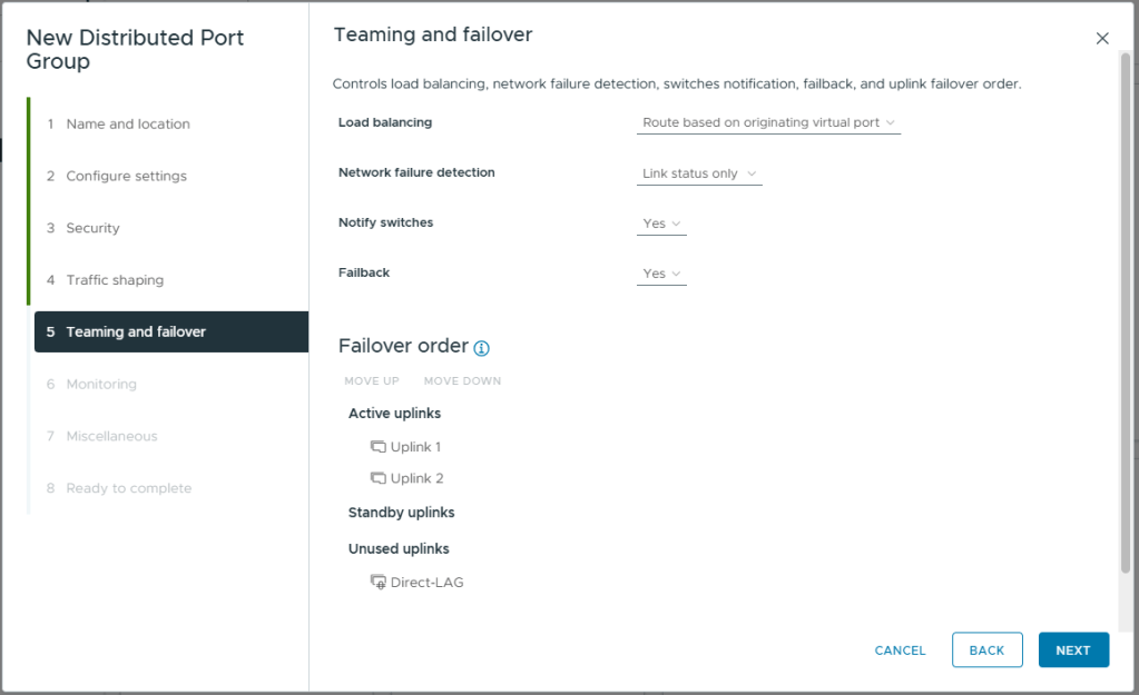
- On Teaming and failover, use the default settings
- Click Next
- On Monitoring, use the default settings
- Click Next
- On Miscellaneous, use the default settings
- Click Next
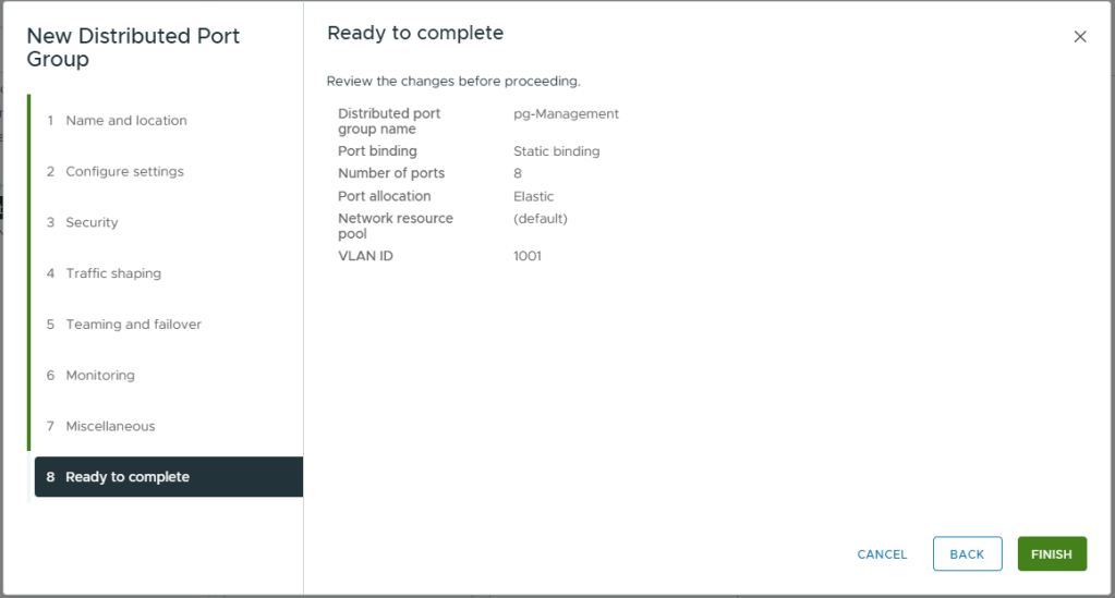
- Review your selections
- Click Finish
- You will see the newly created port group listed
Create the Data Port Group
Finally we will create the Data Port Group. This will follow the same process as for the management port group.
- Right Click on the vDS
- Click Distributed Port Group -> New Distributed Port Group
- On Name and Location, enter a Name: pg-Data
- Click Next

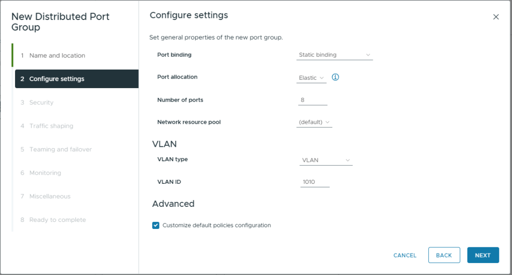
- On Configure settings, use the default settings except
- VLAN Type: VLAN
- VLAN ID: 1010 (or whatever VLAN ID you are using)
- Customized default polices configuration: Checked
- Click Next
- On Security, use the default settings
- Click Next
- On Traffic Shaping, use the default settings
- Click Next
- On Teaming and failover, use the default settings
- Click Next
- On Monitoing, use the default settings
- Click Next
- On Miscellaneous, use the default settings
- Click Next
- Review your selections
- Click Finish

- You will see all four of the newly created port groups listed
Add the host to the vDS
Now we have created the Virtual Distributed Switch, configured a LAG for vSAN and vMotion and created the four Port Groups we will need, it is time to add the host (we only have one host at this stage) to the vDS.
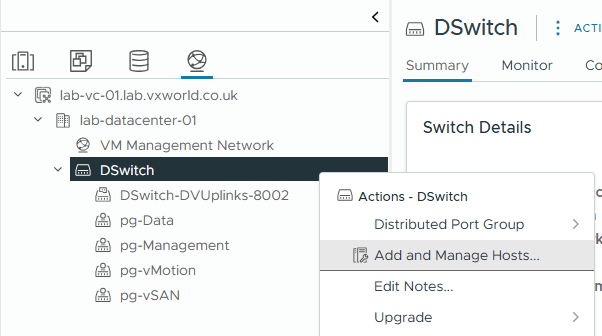
- Right Click on the vDS
- Click Add and Manage Hosts
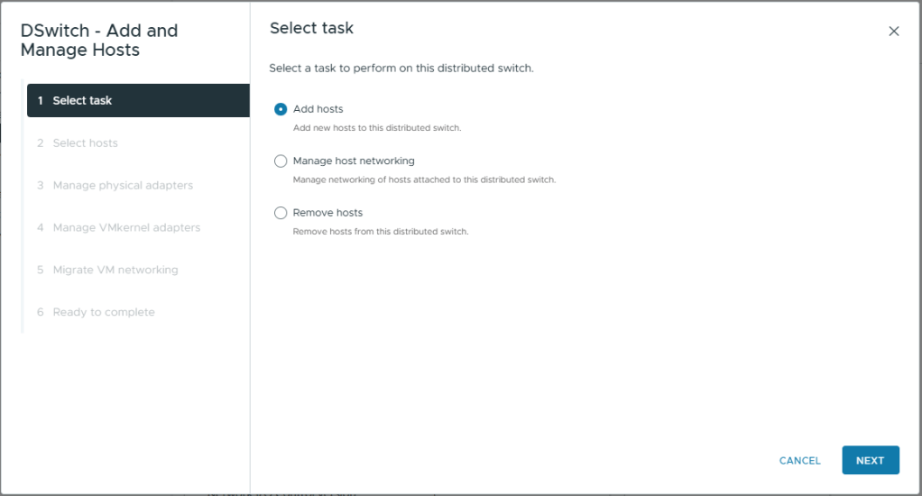
- On Select task, select Add hosts
- Click Next
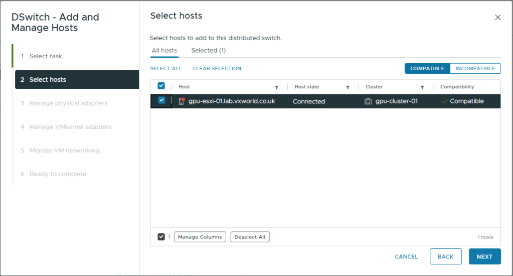
- On Select hosts, select the one and only host
- Click Next
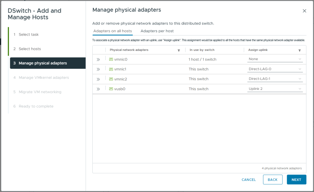
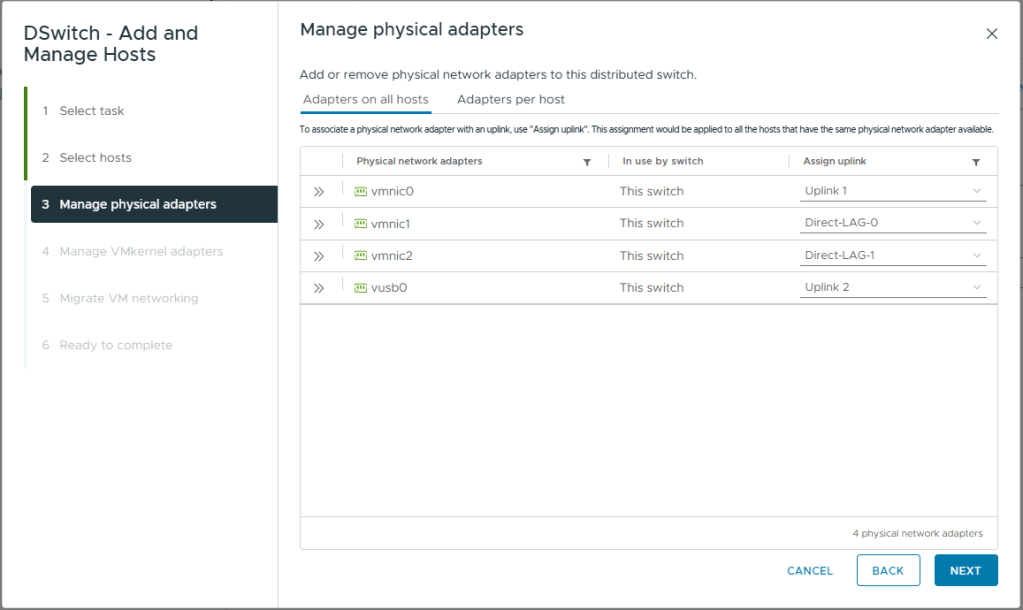
- On Manage physical adapters, map as follows
- vmnic0: None
This vmnic is currently being used for ESXi management traffic. We will migrate it to the vDS after. If we try and do it at the same time, it will fail as vCenter and the host will lose contact - vmnic1: Direct-LAG-0
This is one of the two direct cables between hosts so we will add it to the LAG we created - vmnic2: Direct-LAG-1
This is one of the two direct cables between hosts so we will add it to the LAG we created - vusb0: Uplink 2
This is the currently unused USB NIC in my Homelab. This will be one of two NICs used for management and VM data traffic. With the other being vmnic0.
- vmnic0: None
- Click Next
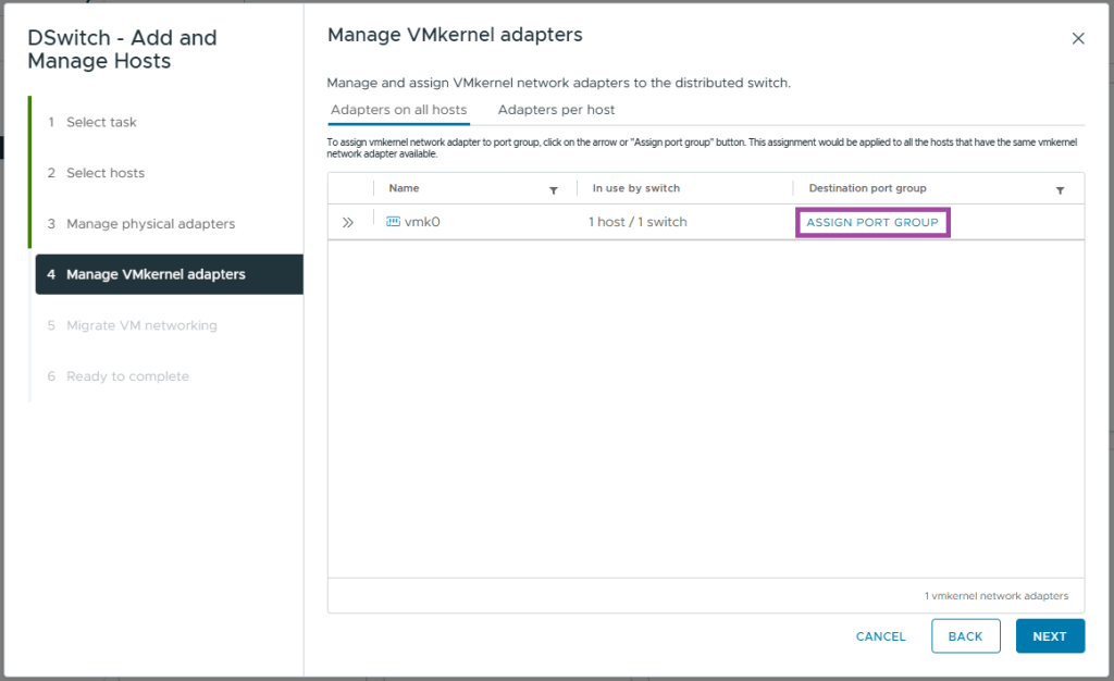
- On Manage VMkernel adapters, for vmk0 click ASSIGN PORT GROUP
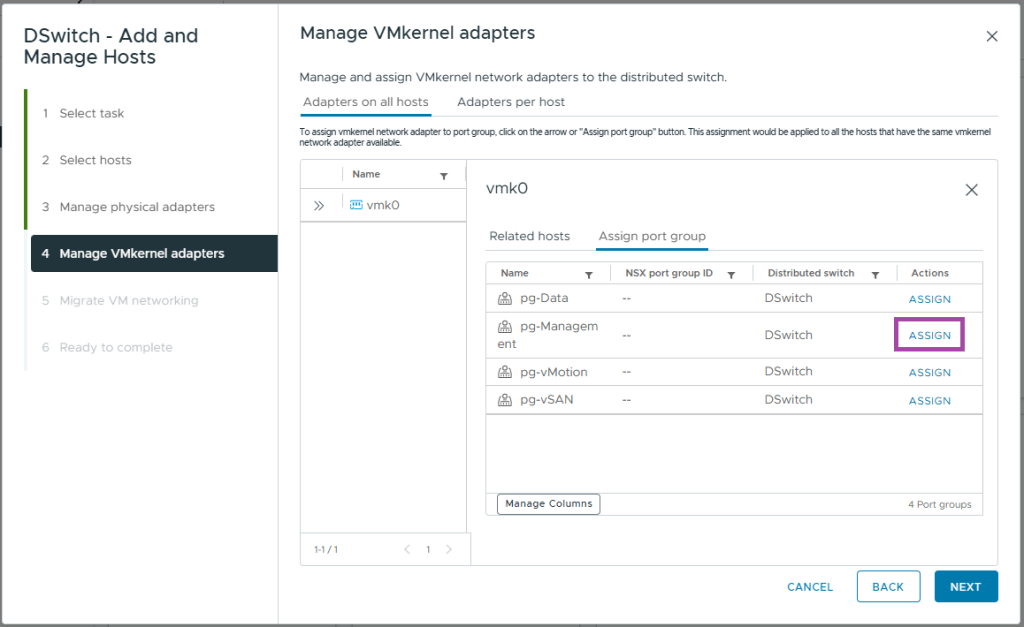
- Locate the pg-Management and Click ASSIGN
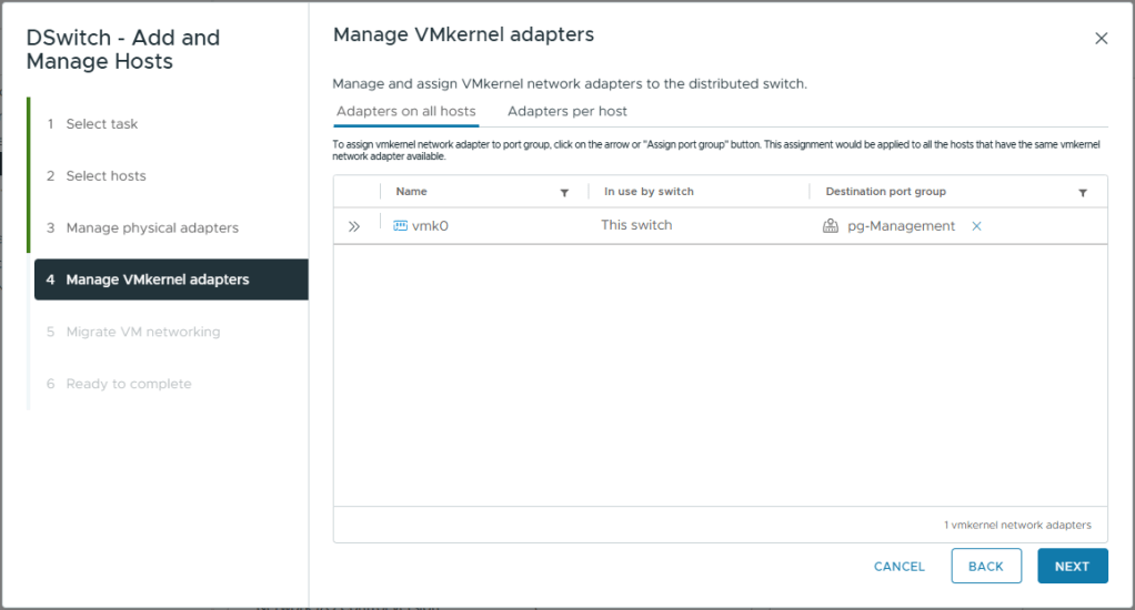
- Close the vmk0 box and you should see the assignment as pictured below
- Click Next
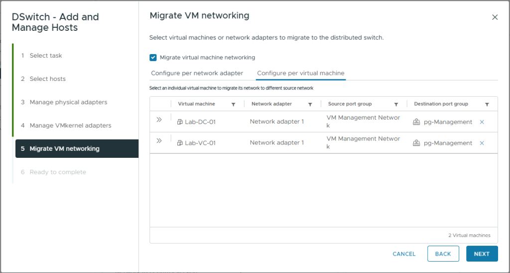
- On Migrate VM networking, select Migrate virtual machine networking
- Click on the Configure per virtual machine tab
- For each of our infrastructure VMs (vCenter and domain controller) assign them to the pg-Management destination port group
- Click Next
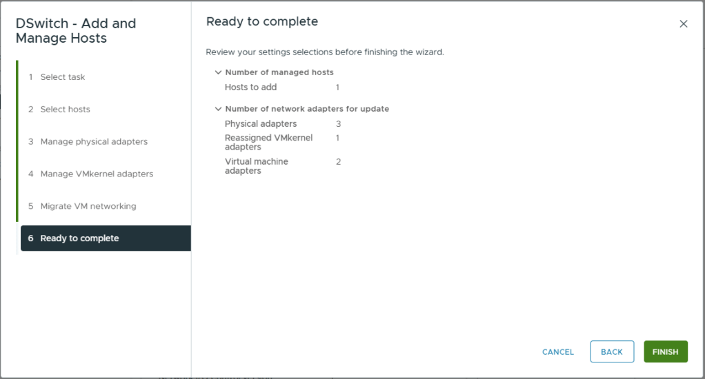
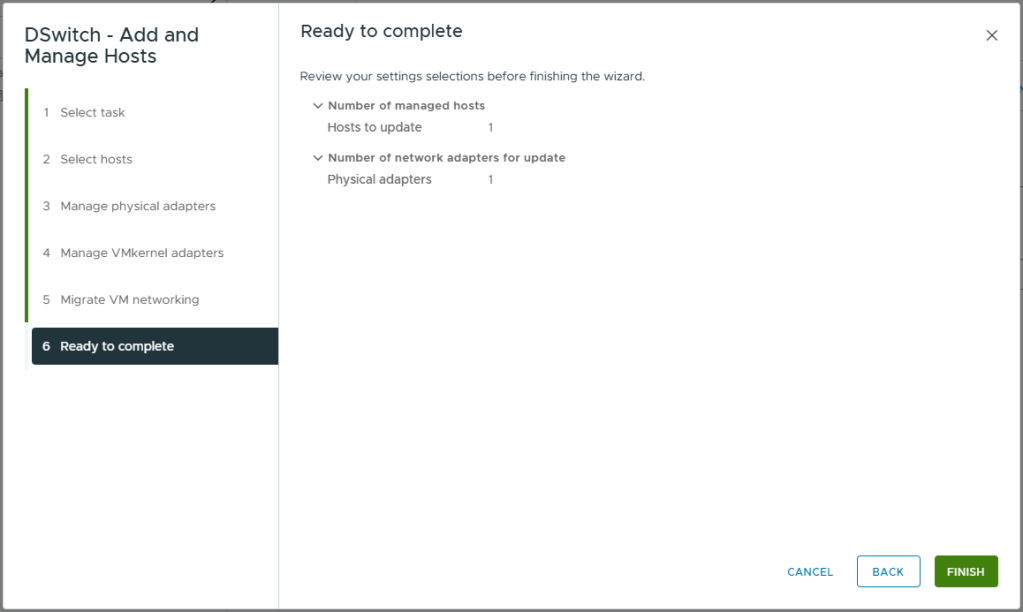
- Review your selections
- Click Finish
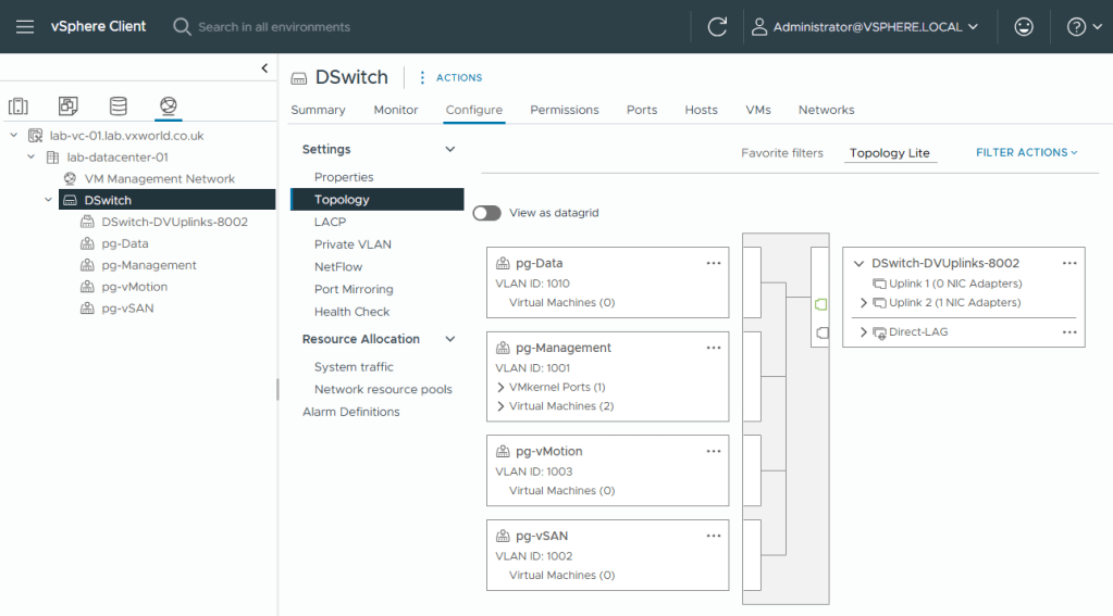
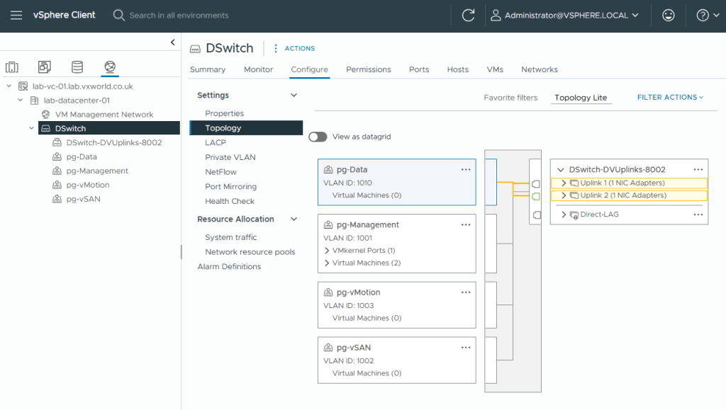
- Once the tasks have completed, if you browse to the [vDS] -> Configure -> Topology, you should see a visual representation of the configuration we have just setup.
- You will note, Uplink 1 has zero adapters. Now we have moved the management VMkernel adapters onto the vDS, we can migrate vmnic0 onto the vDS.
- Right Click on the vDS
- Click Add and Manage Hosts
- Select Manage host networking
- Click Next

- On Select hosts, select the one and only host
- Click Next
- On Manage physical adapters, map vmnic0 to Uplink 1
This will provide the second uplink for management and VM data traffic. All other physical adapters are already mapped to this vDS - Click Next
- On Manage VMkernel adapters, click Next
- On Migrate VM networking, click Next
- Review your selections
- Click Finish
- On the Topology view
- Select pg-Data or pg-Management
- You should see it maps to both uplinks and each uplink has ‘1 NIC Adapters’
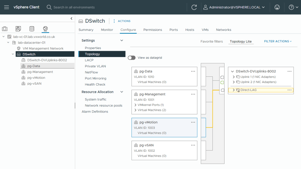
- Select pg-vMotion or pg-vSAN
- You should see it maps to the Direct-LAG
- That concludes creating the Distributed Virtual Switch, associated Port Groups and Migrating one host to it.
- Next we will configure the VMkernel adapters for vSAN and vMotion
Creating other VMkernel adapters
Currently our host only has one VMkernel (vmk0) interface for management. We will now create two additional ones, one for vSAN traffic and one for vMotion traffic. We will also configure the existing one (vmk0) for vSAN Witness traffic.
vSAN
First we will create the VMkernel (vmk1) interface for vSAN.
- Browse to the vSphere Client
- Browse to, Inventory -> Hosts and Clusters View -> [vCenter Server] -> [Cluster ]
- Select the host you need to create the vSAN VMkernel adapters on. You will need to do this for each host you are adding to the cluster. I will be following this same process once I have added my second host.
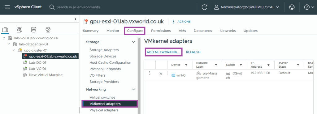
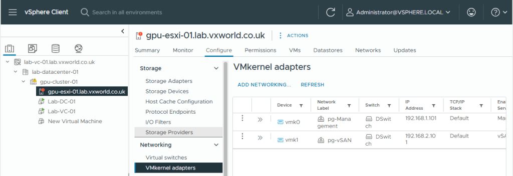
- Browse to, Configure -> Networking -> VMkernel adapters
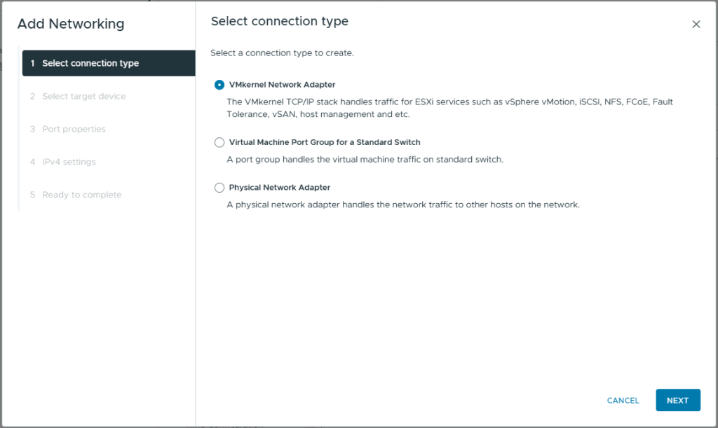
- Click Add Networking
- Select VMkernel Network Adapter
- Click Next
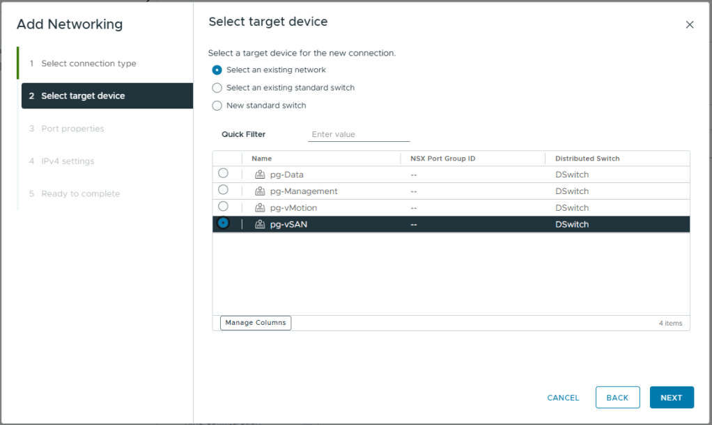
- Select the vSAN port Group we created earlier, pg-vSAN
- Click Next
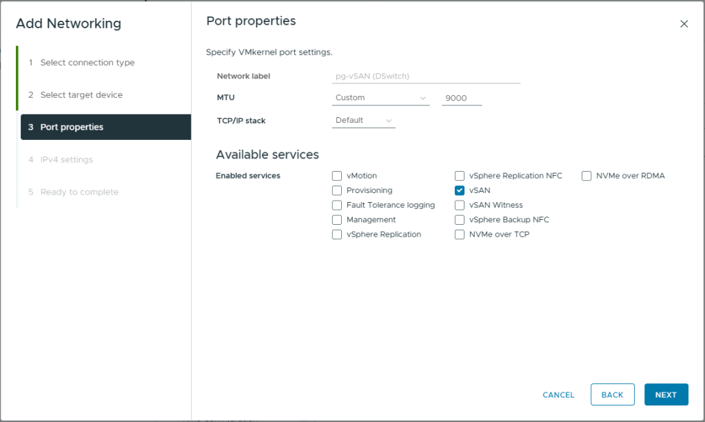
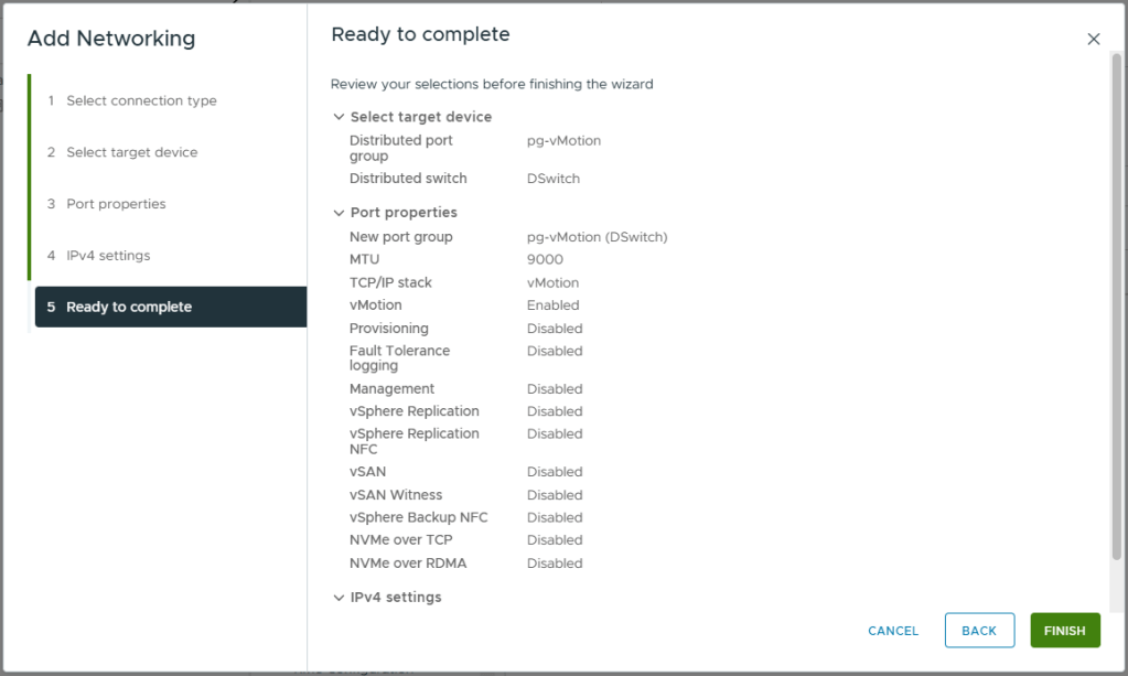
- Enter a MTU of 9000
- Under Enabled Services, select vSAN
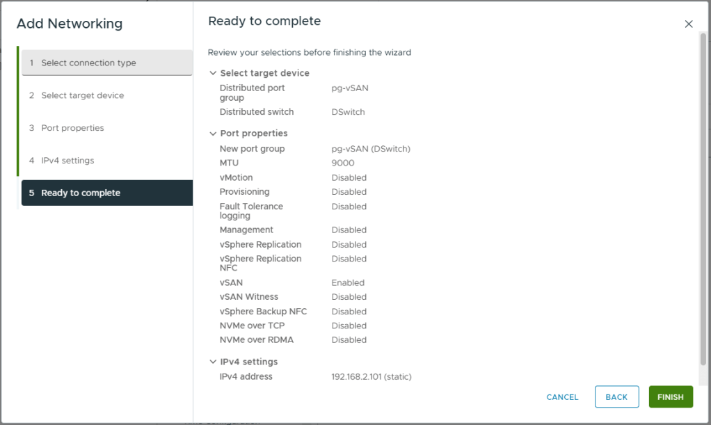
- Click Next
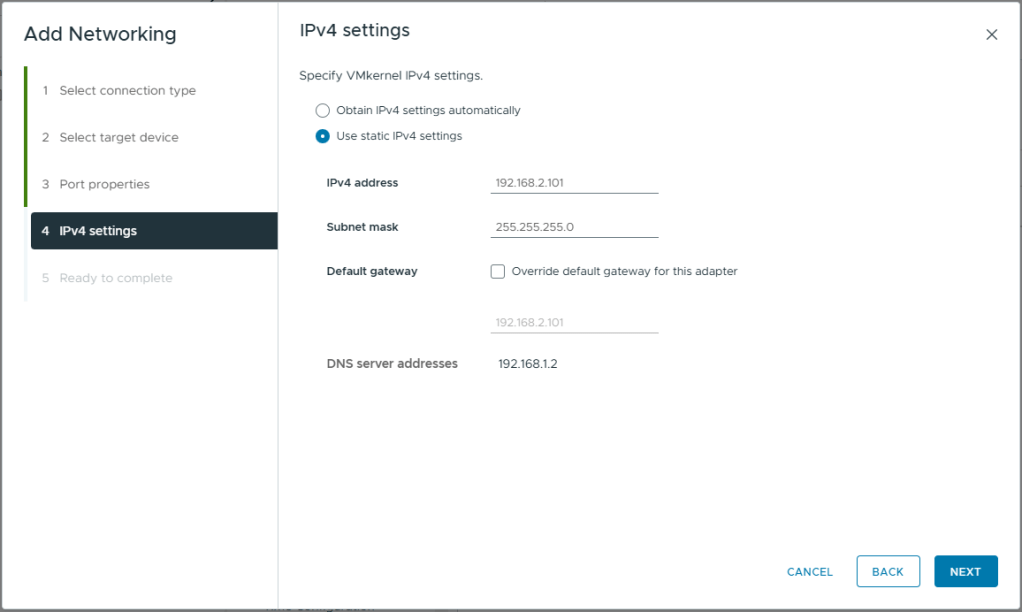
- Select Use static IPv4 settings
- Enter the IPv4 Address for this host. Refer to my logical network diagram at the beginning of this article.
- Enter the Subnet mask for the vSAN network.
- Do not override the default gateway. As this is a two node cluster, with the vSAN network directly connected, I do not have a default gateway available to me on my vSAN network. If your vSAN network is connected via a switch, you might have a valid gateway you can use on the vSAN network, in this case, click override and enter the desired gateway.
- Click Next
- Review your selections
- Click Finish
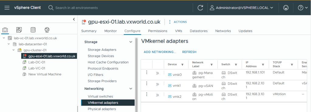
- You should now see vmk1, the newly created vSAN VMkernel adapter listed
vMotion
We will now follow the same process to create the vMotion VMkernel interface (vmk3).
- Browse to the vSphere Client
- Browse to, Inventory -> Hosts and Clusters View -> [vCenter Server] -> [Cluster ]
- Select the host you need to create the vMotion VMkernel adapters on. You will need to do this for each host you are adding to the cluster. I will be following this same process once I have added my second host.
- Browse to, Configure -> Networking -> VMkernel adapters
- Click Add Networking
- Select VMkernel Network Adapter
- Click Next
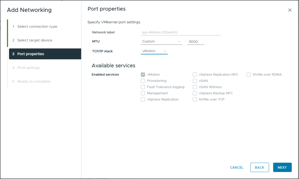
- Select the vMotion port Group we created earlier, pg-vMotion
- Click Next

- Enter a MTU of 9000
- Under TCP/IP Stack, select vMotion. This will auto select vMotion under enabled services and prevent you from adding additional services
- Click Next
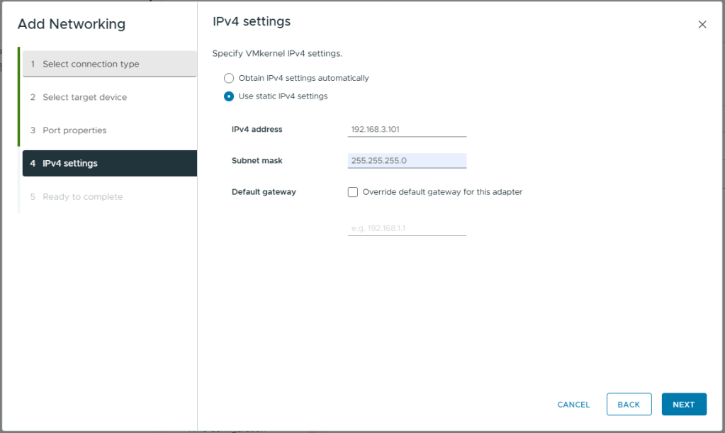
- Select Use static IPv4 settings
- Enter the IPv4 Address for this host. Refer to my logical network diagram at the beginning of this article.
- Enter the Subnet mask for the vMotion network.
- Do not override the default gateway. As this is a two node cluster, with the vSAN network directly connected, I do not have a default gateway available to me on my vMotion network. You would use this setting if you were using a L3 routed network for vMotion (e.g. a stretched cluster)
- Click Next
- Review your selections
- Click Finish
- You should now see vmk2, the newly created vMotion VMkernel adapter listed
Configure Management VMkernel (vmk0) interface for vSAN Witness
Finally, we need to configure the management VMkernel interface (vmk0) for vSAN Witness Traffic. While vSAN data traffic will travel directly between the two hosts over vmk1, each host must also communicate with the witness for heartbeats. This communication will take place over the management adapter, vmk0.
We cannot use the vSAN network for this, not only because it is directly connected in my lab, but also because vSAN data traffic must be prevented from reaching the witness. This is crucial, as the witness is often connected via a slower WAN link compared to the high-speed links between vSAN hosts. To achieve this, the witness resides on a separate Layer 3 network from the vSAN data traffic.
- Browse to the vSphere Client
- Browse to, Inventory -> Hosts and Clusters View -> [vCenter Server] -> [Cluster ]
- Select the host you need to configure the vSAN witness traffic for
- Click the three dots on the management adapter (vmk0)
- Click Edit
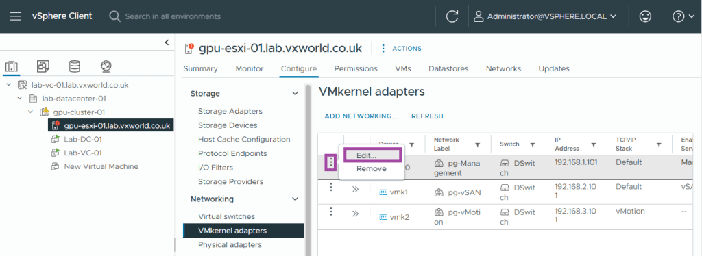
- Check vSAN Witness
- Click OK

Adding additional Host and Witness
We are now ready to add the second host and the witness to form the 2-node vSAN cluster.
If you have not already deployed the witness, check out VMware GPU Homelab: Part 6 – Step-by-Step Guide to vSAN Witness Deployment
Adding the second host
It is assumed you have installed ESXi on the host as per VMware GPU Homelab: Part 3 – Installing ESXi Step by Step and you have configured the network adapters on the second host the same as the first host. If you need a reminder, review the Physical Network Cards section of this post.
- Browse to the vSphere Client
- Browse to, Inventory -> Hosts and Clusters View -> [vCenter Server] -> [Cluster ]
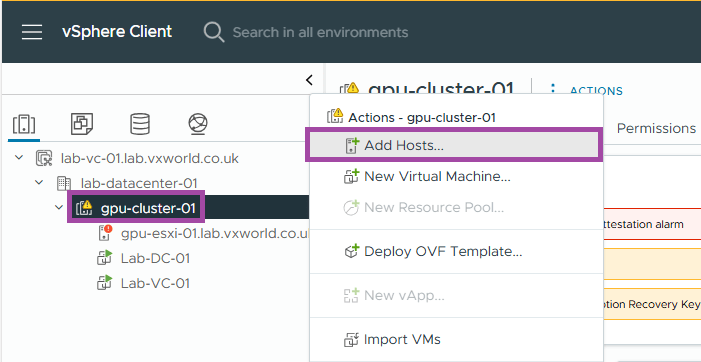
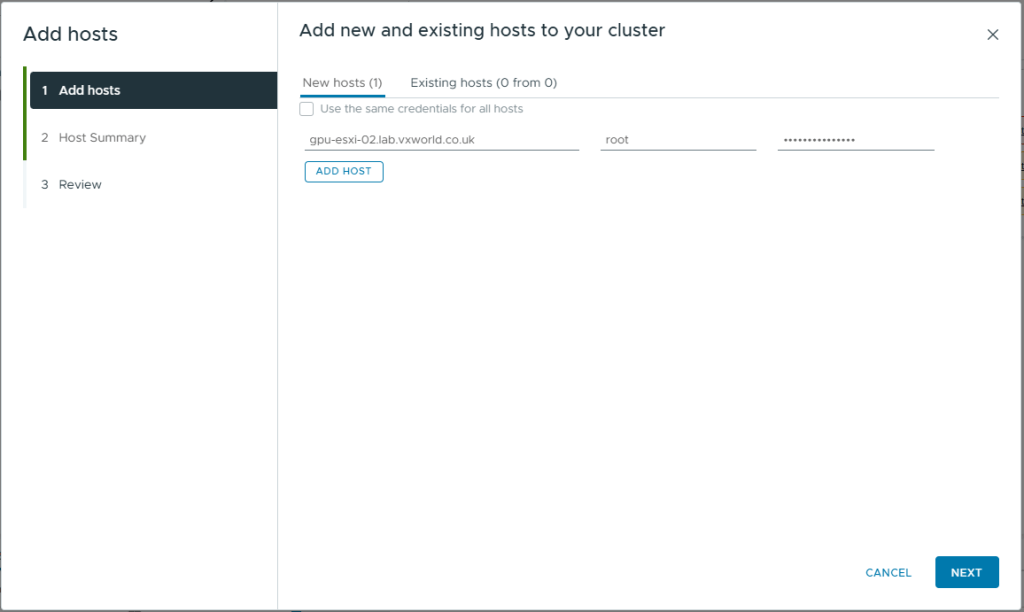
- Right click on the cluster and click Add Hosts
- Enter the FQDN for the second host you want to add to the cluster
- Enter the credentials you setup for the host
- Click Next
TIP
The name you enter determines how the host appears within the vCenter cluster.
For example, if you enter the ESXi host’s hostname or FQDN, it will be displayed that way in vCenter. However, if you use the IP address, the host will be identified by IP, which can make daily management more challenging.
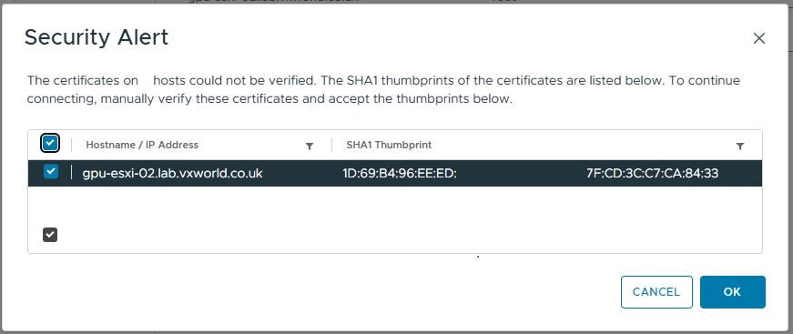
- Review the Security Alert. If the Thumbprint is the one you expect, select it.
- Click OK
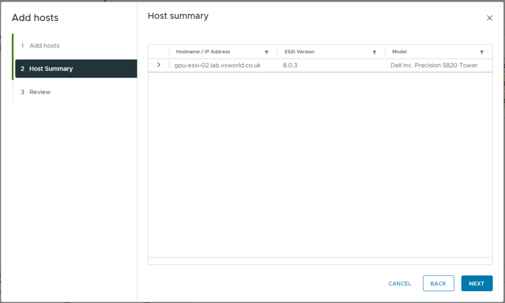
- If you have entered the details correctly and the host is accessible, you should see the Host summary like below
- Click Next
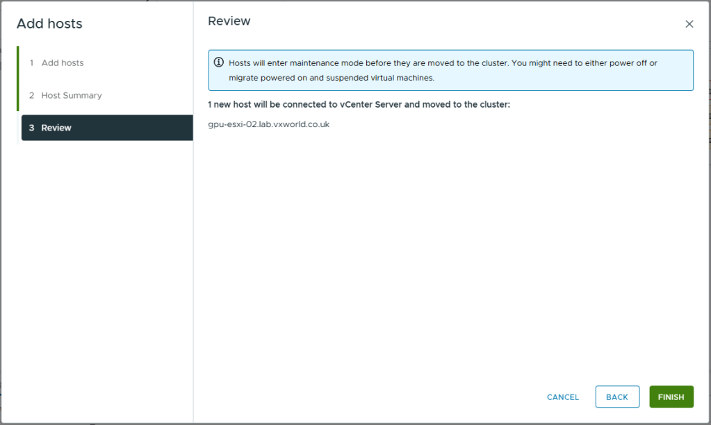
- Review the impact
- Click Finish
Configure networking on the second host
Now the second host has been added to the cluster, we need to perform some of the same processes we did earlier on the first host (not the witness).
- Follow the process to add the second cluster host to the vDS, Add The Host To The vDS. NOTE: There should be no Virtual Machine networking to migrate this time
- Follow the process to create the VMkernel adapters for vSAN and vMotion did earlier on the first host, Creating Other VMkernel Adapters
You should now have both hosts in the cluster and they should be able to talk to each other.
Add the Witness to vCenter
It is now time to add the witness we deployed earlier to vCenter. Note, we are adding it to vCenter not the cluster!
- Browse to the vSphere Client
- Browse to, Inventory -> Hosts and Clusters View -> [vCenter Server]
- Right click on the data centre and click Add Hosts
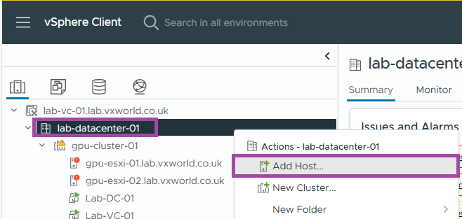
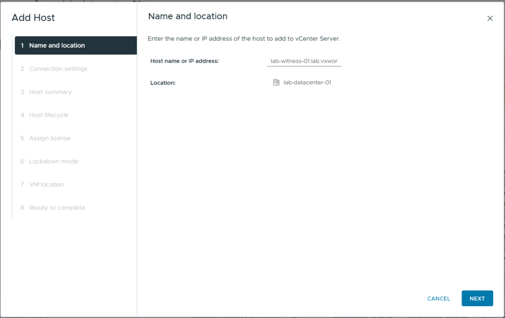
- Enter the FQDN of the witness
- Click Next
TIP
The name you enter determines how the host appears within the vCenter cluster.
For example, if you enter the witness’s hostname or FQDN, it will be displayed that way in vCenter. However, if you use the IP address, the witness will be identified by IP, which can make daily management more challenging.
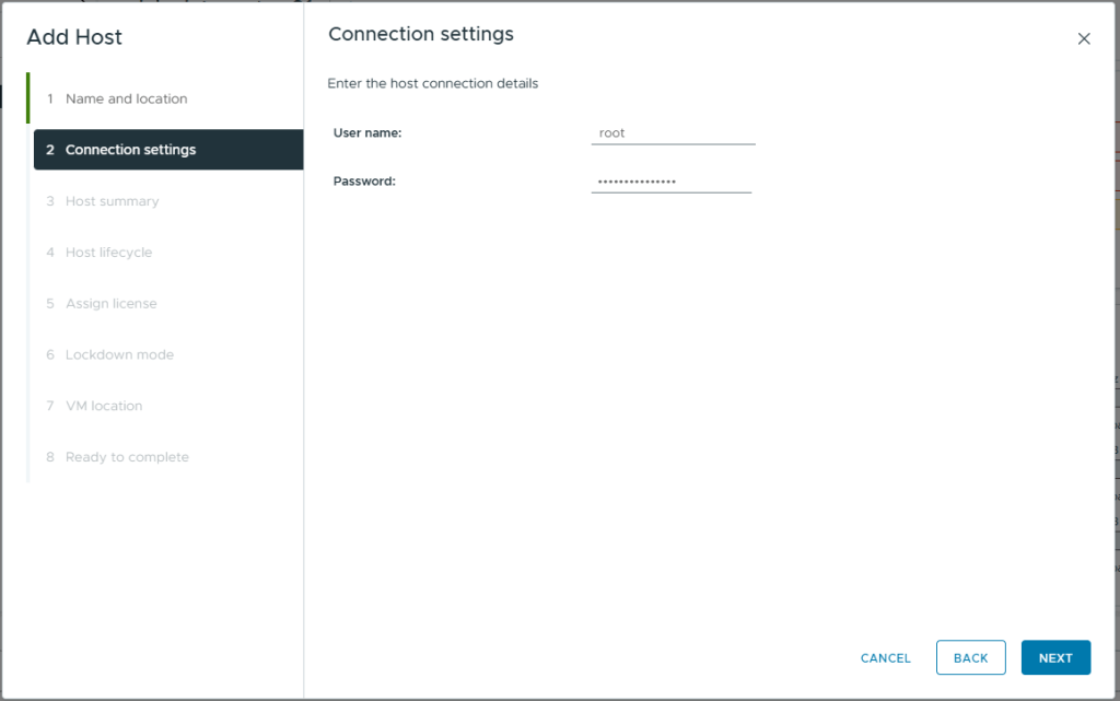
- Enter the credentials you setup for the witness
- Click Next
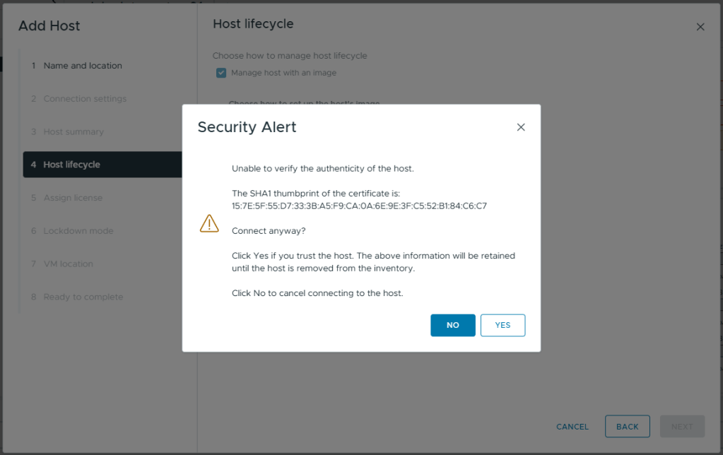
- If you get a Security Alert
- Check if the Thumbprint is the one you expect, if it is, select it.
- Click OK
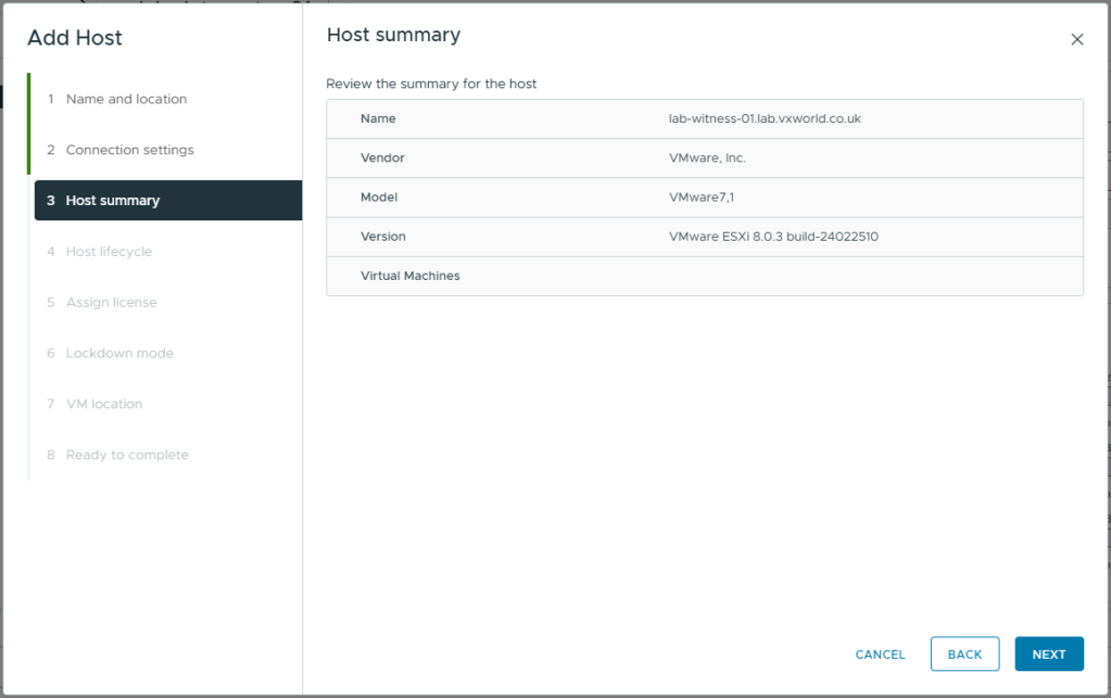
- Review the host summary
- Click Next
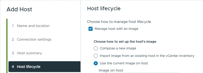
- Select Manage host with an image
- Select Use the current image on host
- If you get a Security Alert, check if the Thumbprint is the one you expect, if it is, click Yes
- Click Next

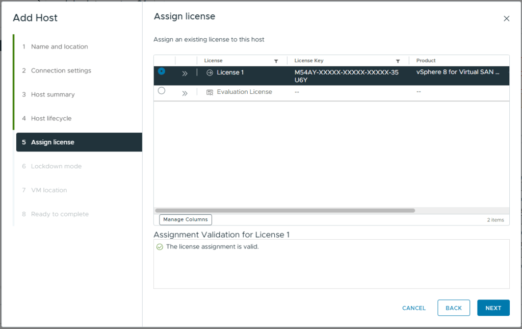
- On the assign license screen. A Virtual SAN Witness license should already be assigned.
- Click Next
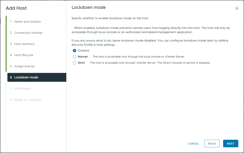
- Leave the lockdown mode as Disabled. As this is a Homelab, we do not need the added security. In production, this option needs reviewing and understanding.
- Click Next
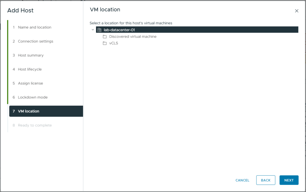
- Select the datacentre as the VM location. As there are no VMs on this ESXi witness host, this is irrelevant.
- Click Next
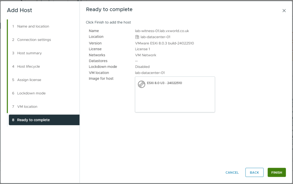
- Review the summary
- Click Finish
- After a short while, the whiteness should be displayed in the inventory
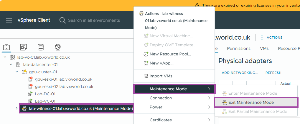
- Now we are going to take the witness out of maintenance mode
- Right click on the vSAN witness
- Click Maintenance Mode -> Exit Maintenance Mode
Create the vSAN stretched cluster
To recap, we have two hosts in a cluster and a witness in vCenter, it is now is it time to create the vSAN stretched cluster.
- Browse to the vSphere Client
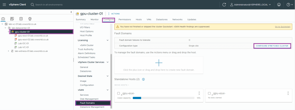
- Browse to, Inventory -> Hosts and Clusters View -> [vCenter Server] -> [Datacentre] -> [Cluster]
- Browse to, Configure -> vSAN -> Fault Domains
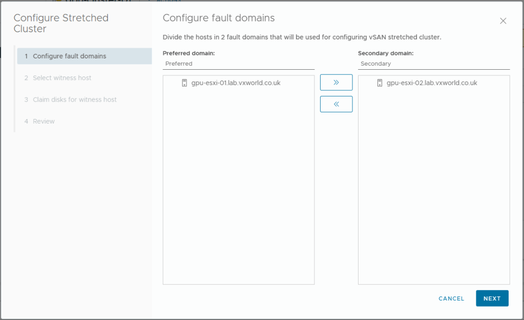
- Click Configure Stretched Cluster
- Put one host in the preferred domain and one if the secondary domain
- Click Next
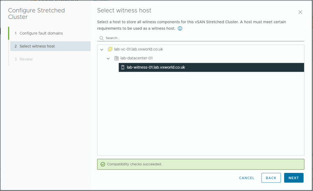
- Select your witness
- Click Next
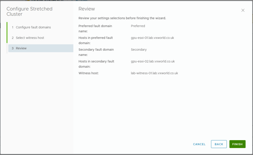
- Review your selections
- Click Finish
- You can monitor the progress, you should see a number of tasks in the Recent Tasks panel at the bottom.
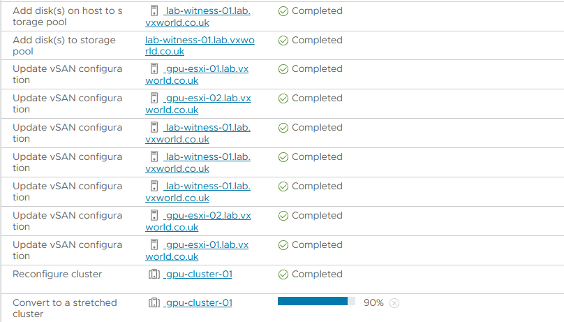
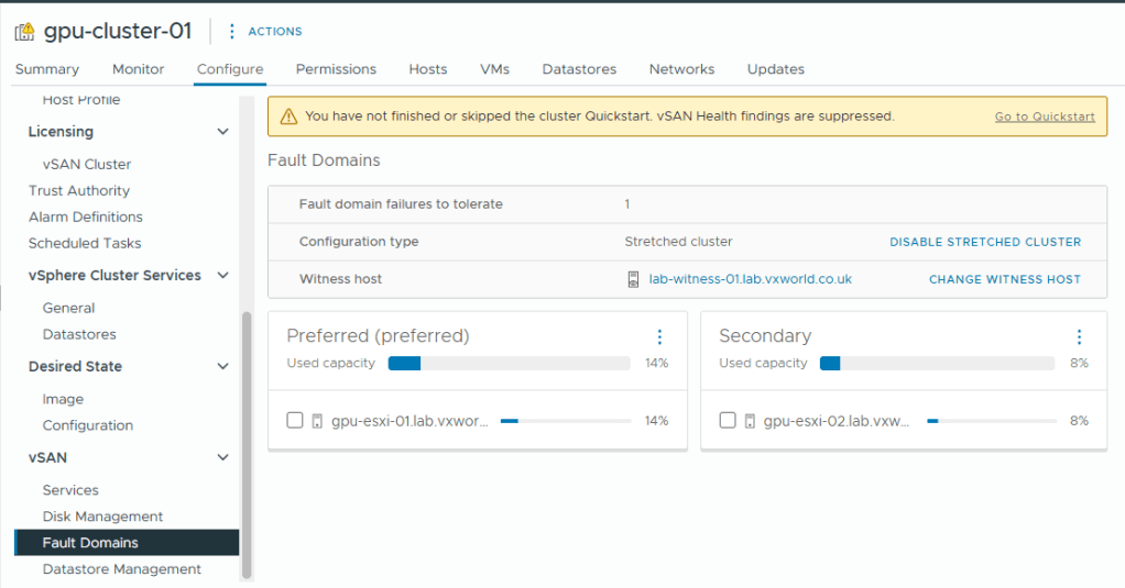
- After a while you should see the two fault domains and witness like below
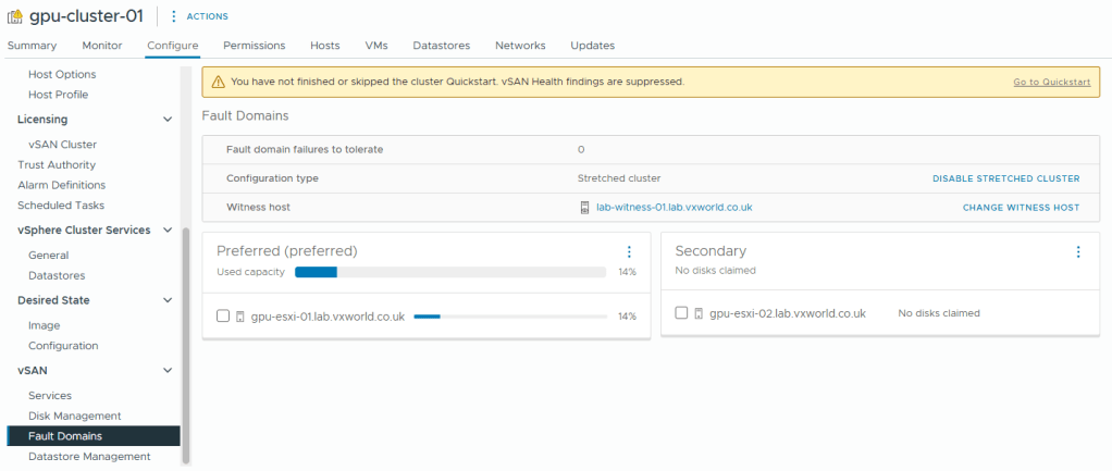
- Not in the screenshot above, the second host does not have any disks. We now need to claim the disks in that host to use for vSAN. If you are using supported disks, they should have claimed automatically.
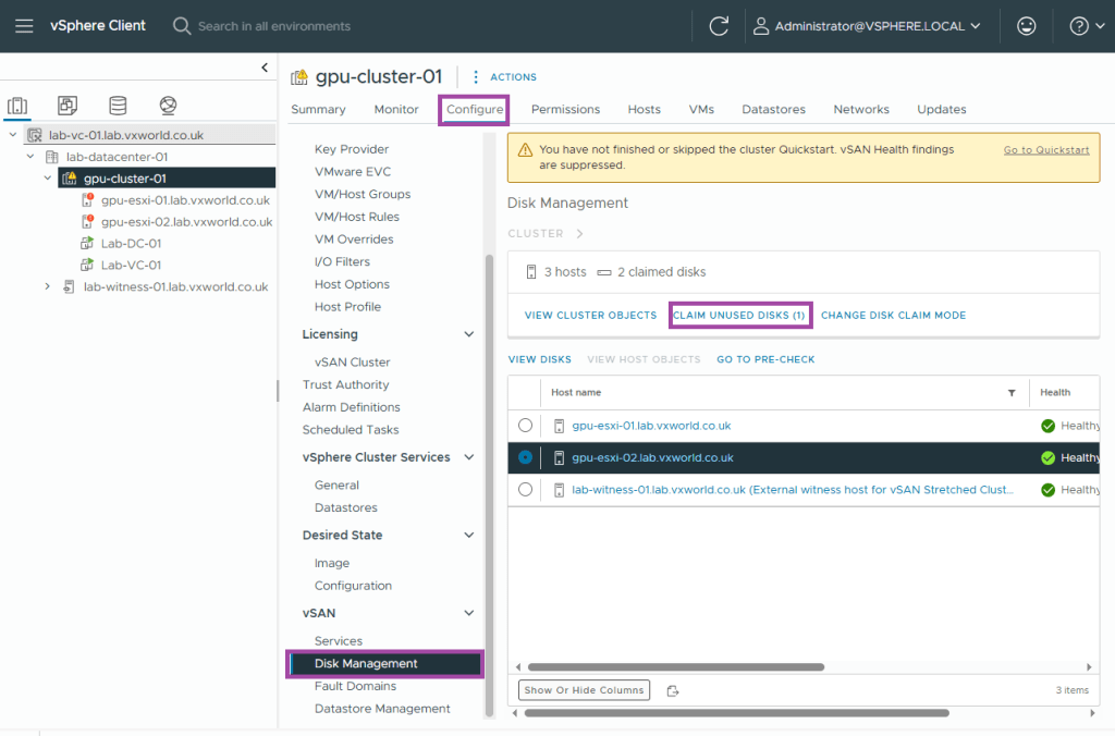
- Browse to, Configure -> vSAN -> Disk Management
- Click Claim Unused Disks
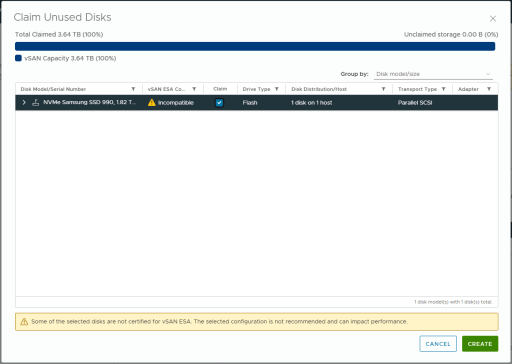
- Check the Claim box for any disks you want to add to vSAN. The reason this did not happen automatically is my host is using a disk (Samsung 990 Pro) that is not on the vSAN ESA Hardware Compatibility List
- Click Create
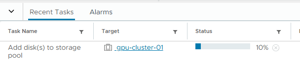
- It can take a little while to add the disks to the storage pool. Progress can be monitored in the Tasks pane.
- Browse to, Configure -> vSAN -> Fault Domains
- We can now see there is usable capacity in both the Preferred and Secondary site
- We now have a 2-node vSAN ESA cluster, it is time to give it a health check and resolve any outstanding issues.
Resolve outstating vSAN issues
We are now going to use quick start to identify the outstanding actions.
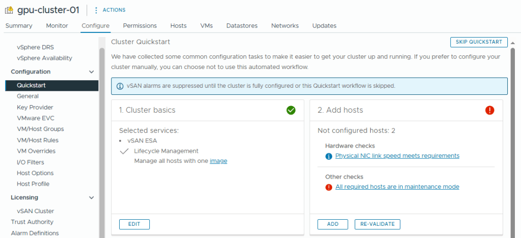
- Browse to, Configure -> Configuration -> Quickstart
- Review the issues under Add hosts
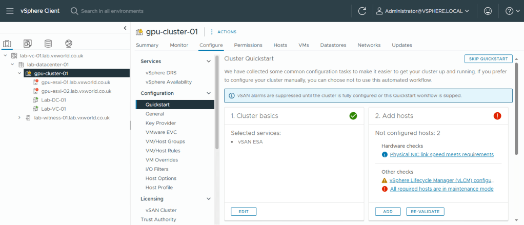
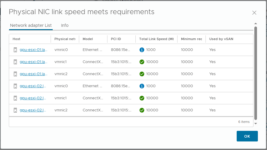
- The Physical NIC link speed meets requirements alert. This is flagging vmnic0 link speed. It is saying they are used by vSAN (presumably due to the vSAN witness traffic). I believe this is a false positive as my vSAN data uses vmnic1 and vmnic2, therefor I will ignore this informational alert.
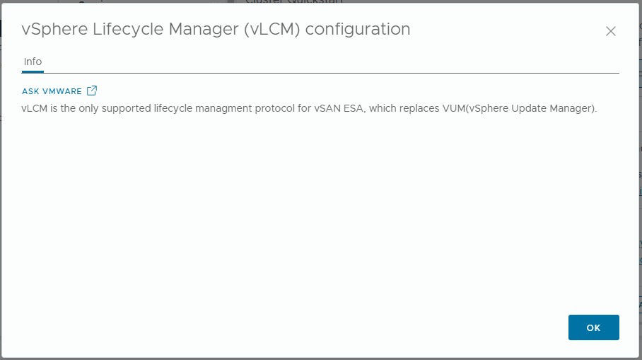
- The vSphere Lifecycle Manager (vLCM) configuration alert. This is because I have not yet configured vLCM. Lets setup vLCM to use images.
- Browse to, Inventory -> Hosts and Clusters View -> [vCenter Server] -> [Datacentre] -> [Cluster]
- Browse to, Updates -> Hosts -> Images
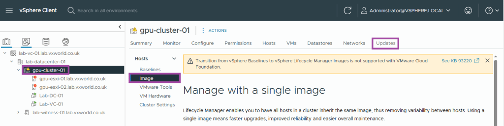
- A common image will be identified from the cluster hosts.
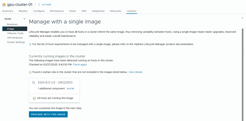
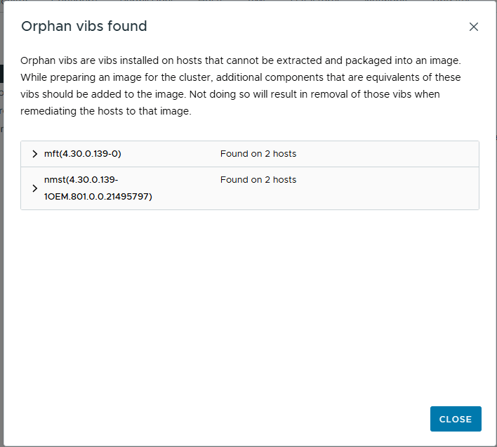
- You can view the additional components it finds (in my case, the USB NIC Fling VIB) and any orphan vibs like the example below
- Click Proceed with this image
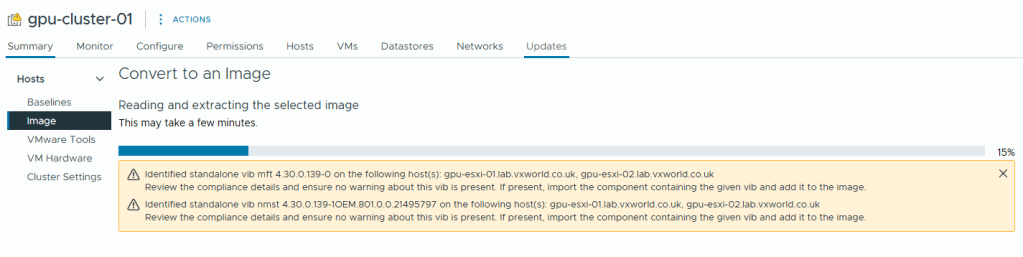
- The image will then be extracted
- As I am using workstations rather than vSAN ReadyNodes, there are no Vendor Addon’s to add.
- Again Firmware and Driver Addons are not applicable, I would need enterprise hardware connected to a Hardware Support Manager (HSM) e.g. Dell OpenManage
- Click Save
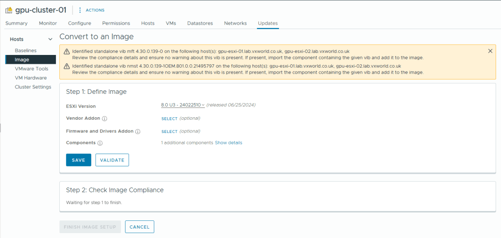
- Click Finish Image Setup
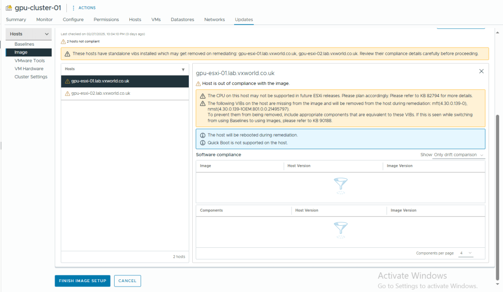
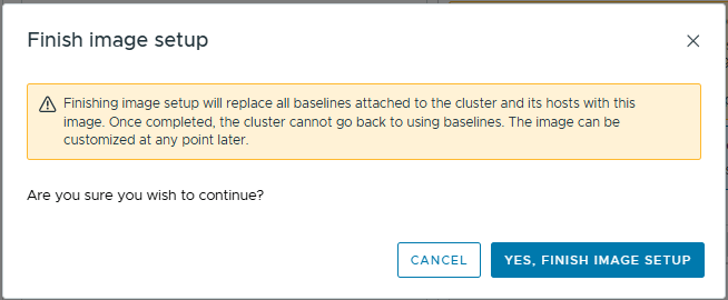
- Click Yes, Finish Image Setup
- At some point, we need to remediate our hosts. However as vSAN is not fully operational and our data is not redundant, trying to remediate now would fail.
- We will now go back to the Quickstart to see if that cleared the vLCM error
- Browse to, Configure -> Configuration -> Quickstart
- Review the issues under Add hosts
- As you can see, the vSphere Lifecycle Manager (vLCM) configuration alert has cleared.
- The All required hosts are in maintenance mode alert shows I took the second host out of maintenance before I should have. I have corrected the instructions so you will hopefully not see this issue.
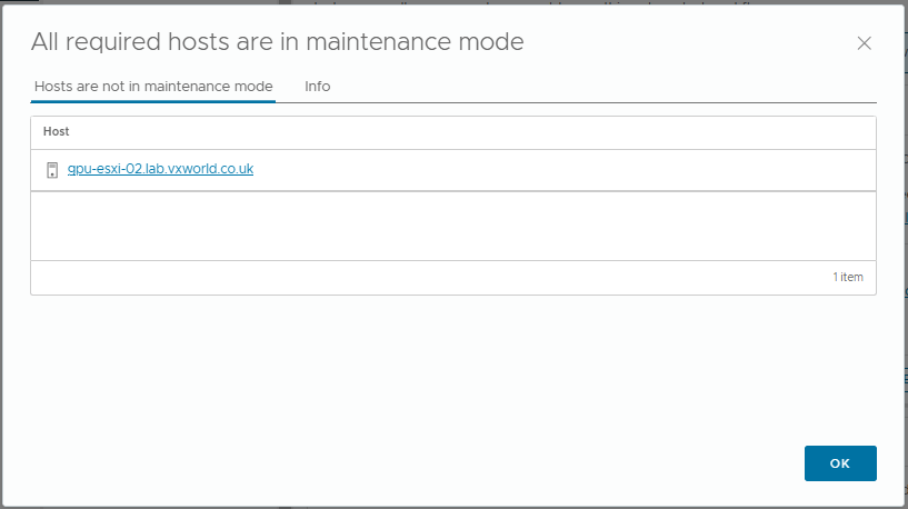
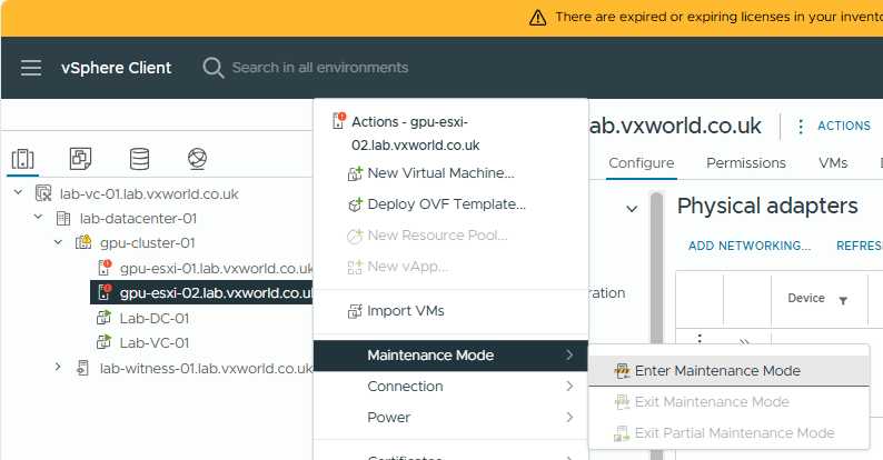
- I am going to put the host back into maintenance mode
- Select Ensure Accessibility
- Click OK
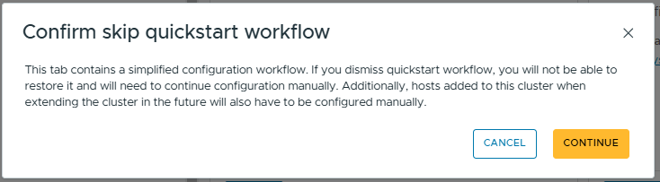
- Going back to Quickstart, I can see all the issues have been resolved and I can click Skip Quick start (because I want to set things up manually to have a better understanding)
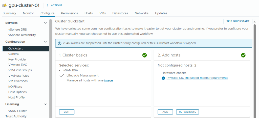
- Click Continue to skip the quick start workflow
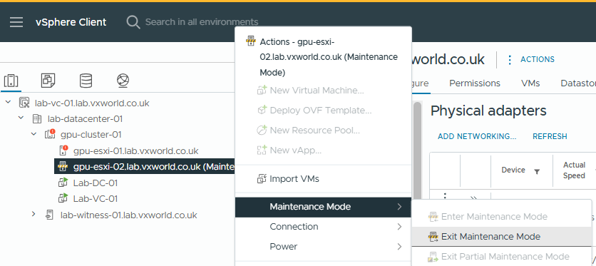
- Now it is time to take the second host out of maintenance mode.
- Right click on the host
- Click Maintenance Mode -> Exit Maintenance Mode
Configure the vSAN Policy
We now need to ensure all the vSAN objects on the Datastore are replicated between the two hosts. You can create a new policy and assign that as the default policy. However as this is a lab, I am going to edit the existing default policy. In production, I would create a new one and link it to the vSAN datastore.
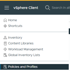
- Click the hamburger menu in the vSphere Client
- Click Policies and Profiles
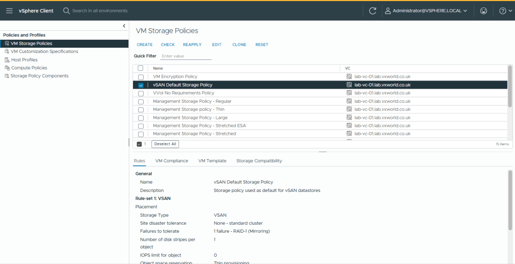
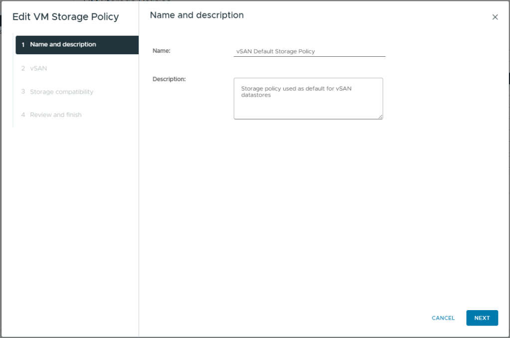
- Select vSAN Default Storage Policy
- Click Edit
- Click Next
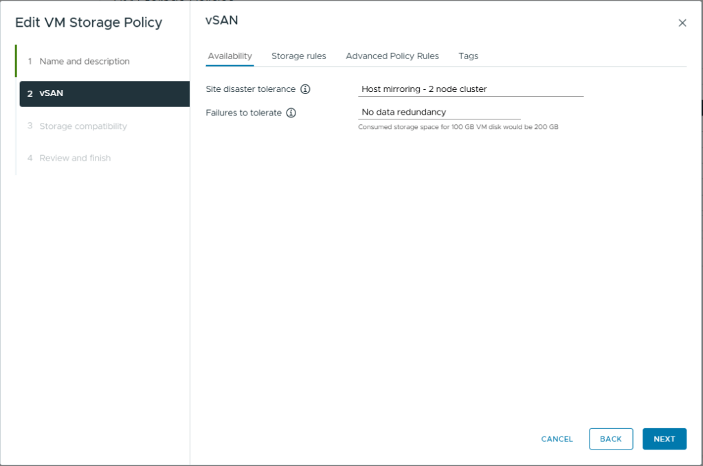
- Change the Site disaster tolerance to, Host mirroring – 2 node cluster. This will create a RAID 1 mirror across the two hosts with the witness component being placed on the ESXi witness node.
- Failure to tolerate, No data redundancy. In a two node cluster, this is know as secondary failures to tolerate or nested fault domains. This would require a minimum of 3 NVME drives in each host. I only have one in my lab so this is not an option.
- Click Next
If you want more details on Storage Policies check out Data placement with vSAN Storage Policies
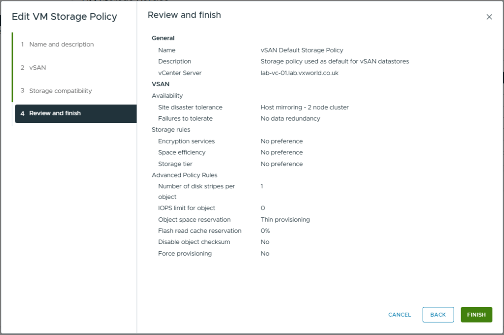
- Click Next
- Click Finish
- After some time, the policy should trigger components to be replicated across both hosts. In the next bit, we will check the vSAN status and component placement.
Checking vSAN Status
- Browse to one of your VMs deployed onto the vSAN datastore.
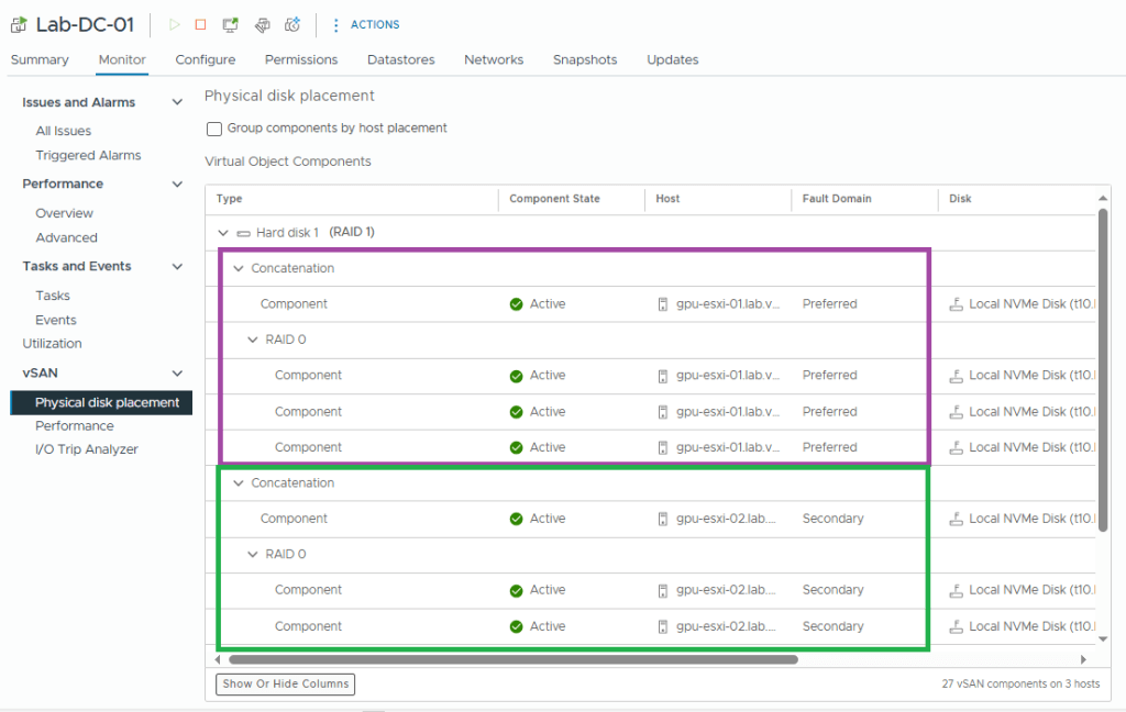
- Browse to, Monitor -> vSAN -> Phyisical disk placement
- You should see a RAID 1, with a Concatenation located on both Preferred (purple box) and Secondary (green box) fault domains.
- If you scroll further down than my screenshot, you should also see the witness component.
- Next we will check vSAN Skyline Health
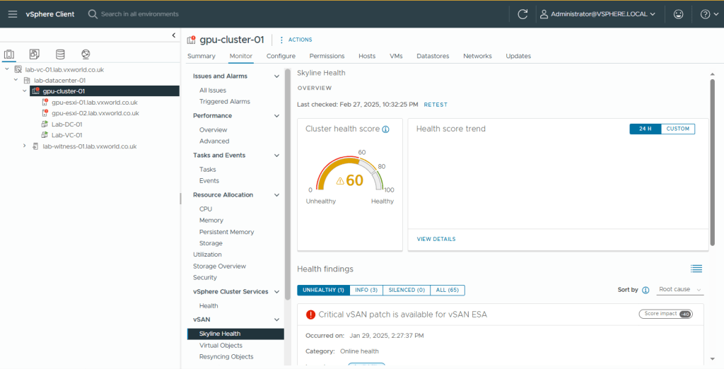
- Select the cluster
- Browse to, Monitor -> vSAN -> Skyline Health
- As you can see, my Health is 60, the main issue is a Critical vSAN patch. Therefore I will remediate my cluster to use a later ESXi version.
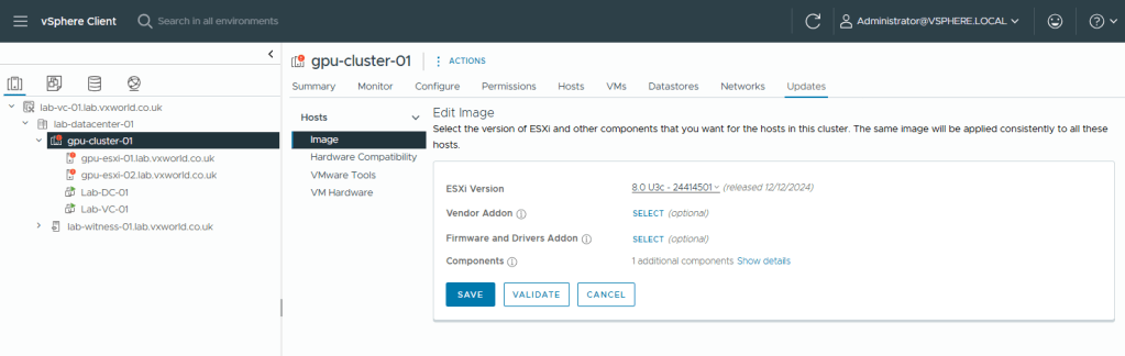
- Browse to Updates-> Image
- Click Edit
- Select a later ESXi version, in my case I selected 8.0U3c
- Click Save
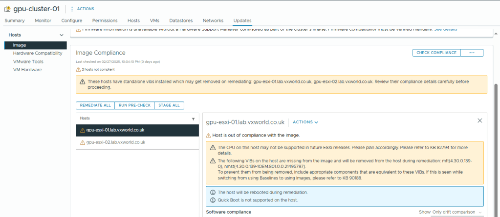
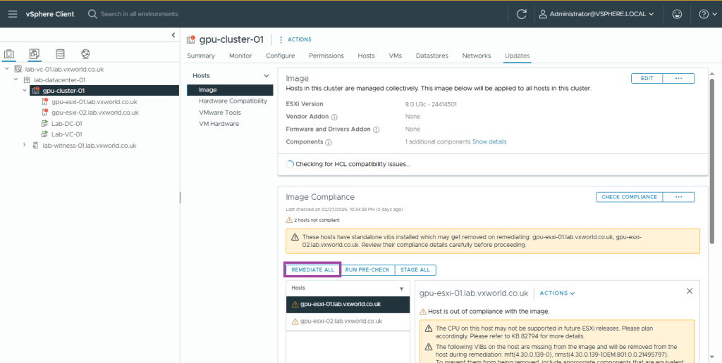
- Next we need to remediate the two hosts. As I do not currently have DRS enabled (it would automatically vMotion VMs when a host goes into maintenance mode), I will remediate each host one by one, moving all VMs off prior to remediation.
- If you have DRS enabled, click Remediate All (as per the screenshot). If like me, it is not enabled yet, first vMotion the VMs off the host manually, they select the host as pictured below and lick the ACTIONS dropdown, then select remediate.
TIP
If you want to enable DRS first, in the next section in this post. This would allow you to click remediate all
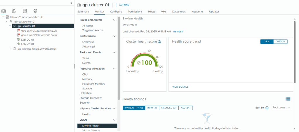
- Once you have remediated both, select the cluster and return to, Monitor -> vSAN -> Skyline Health
- Hopefully your Skyline Health now shows 100%
Distributed Resource Scheduler (DRS)
vSphere Distributed Resource Scheduler (DRS) is a feature in VMware vSphere that automatically balances workloads across hosts in a vSphere cluster to optimise performance and resource utilisation. This includes initial placement when a VM is powered on, automatically migrating VMs when a host becomes contended for CPU, and evacuating a host when it enters maintenance mode.
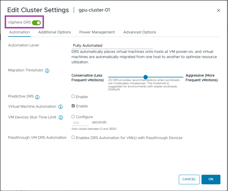
The level of automation is configurable, but I will be using the default settings, Fully Automated. Additionally, you can configure overrides for individual VMs to customise their behaviour within the DRS policy.
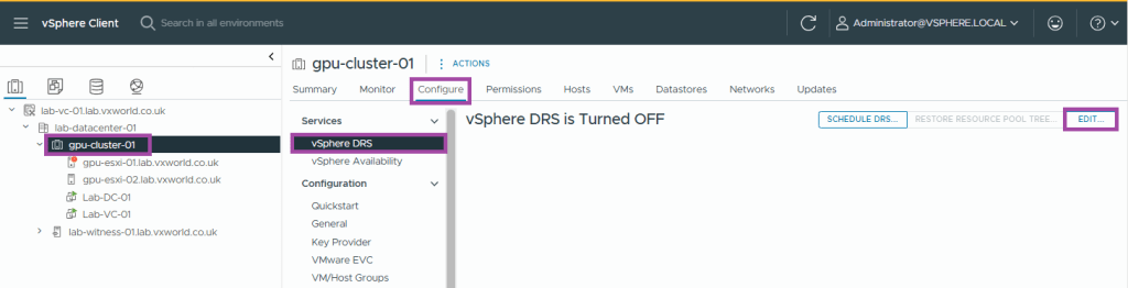
- Select the cluster
- Browse to, Configure -> Services -> vSphere DRS
- Click Edit
- Toggle the vSphere DRS button to enable it (green)
- Click OK
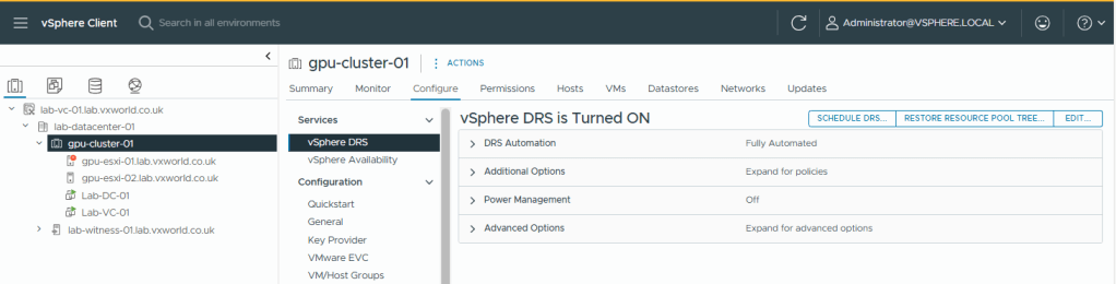
- You should now see vSphere RDS is Turned ON
- DRS should now be working. You can test this by putting a host into maintenance mode if you want. You should see any VM running on it live migrated (vMotion) onto the other host.
High Availability (HA)
vSphere HA (High Availability) is a feature in VMware vSphere that provides automated failover for virtual machines (VMs) in case of host failure(s), ensuring minimal downtime and improved reliability. In a 2-node cluster, we cannot use the Host Isolation response as it will not be able to correctly detect a Host Isolation event. However, vSAN will provide this capability for us and kill the VMs in the event of a vSAN partition.
The isolation response is not required for 2-node as it is impossible to properly detect an isolation event and vSAN has a mechanism to do exactly what the Isolation Response does: kill the VMs when they are useless
This host has no isolation addresses defined as required by vSphere HA
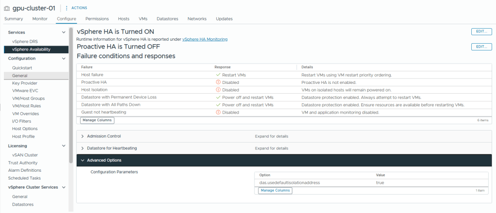
The settings we need to correctly configure HA in a 2-node cluster are as follow
- Set the HA isolation response to Disabled (leave powered on)
- If it das.usedefaultisolationaddress is configured, set it to true (I will set it to true to show its an explicit dission)
- Have a gateway set on the management vmkernel. (Alternatively, you could set das.isolationaddress to 127.0.0.1 and set das.usedefaultisolationaddress to false, preventing ‘This host has no isolation addresses defined as required by vSphere HA’ the error from popping up)
So why are we setting the Isolation Response to disabled? On a vSAN cluster you normally set it to ‘Power off and restart VMs’ – I think the except from Yellow Bricks sums it up nicely.
Disable the Isolation Response >> set it to “disabled” (leave powered on)
That probably makes you wonder what will happen when a host is isolated from the rest of the cluster (other host and the witness). Well, when this happens then the VMs are still killed, but not as a result of the isolation response kicking in, but as a result of vSAN kicking in
Right, lets setup HA!
- Select the cluster
- Browse to, Configure -> Services -> vSphere Availability
- Click Edit
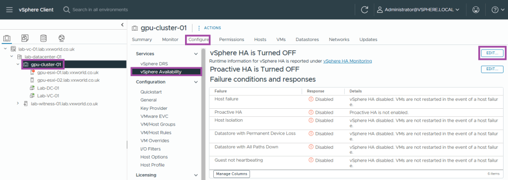
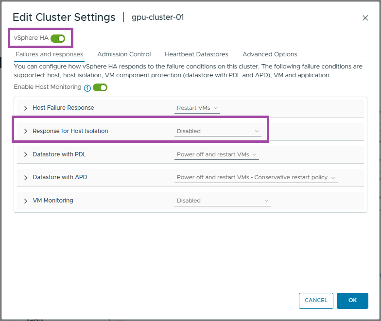
- Enable vSphere HA
- Set the Response to Host Isolation to Disabled
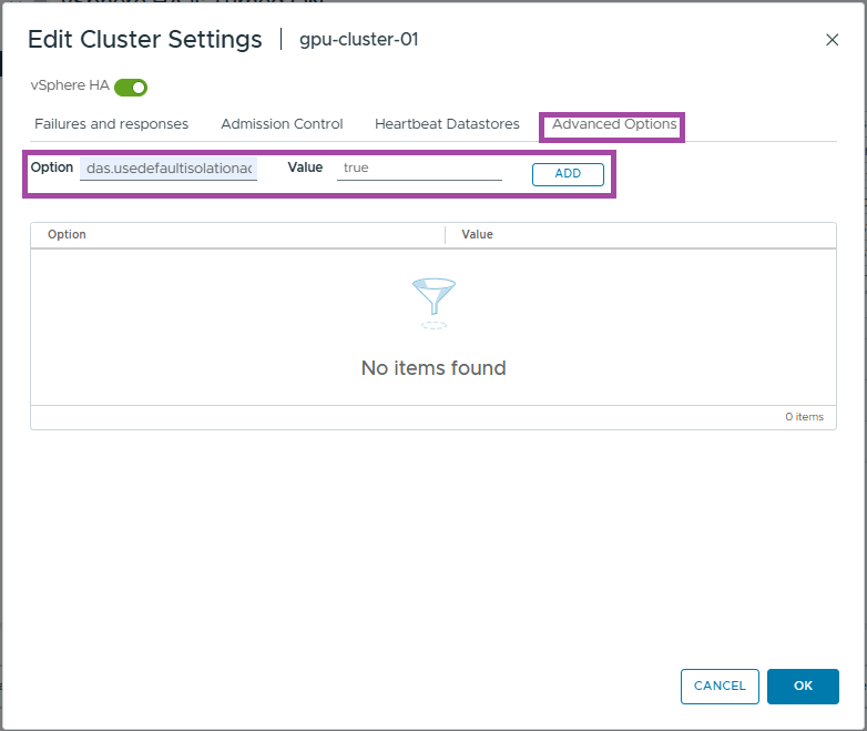
- Click Advanced Options
- Enter das.usedefaultisolationaddress as the option
- Enter true as the value
- Click Add
- Click OK
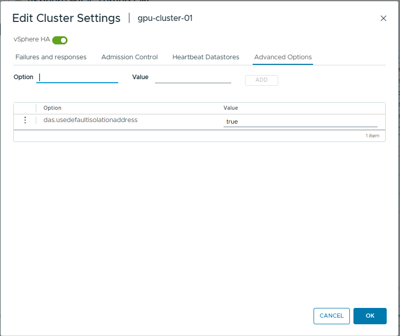
- You should now see the HA settings we just configured
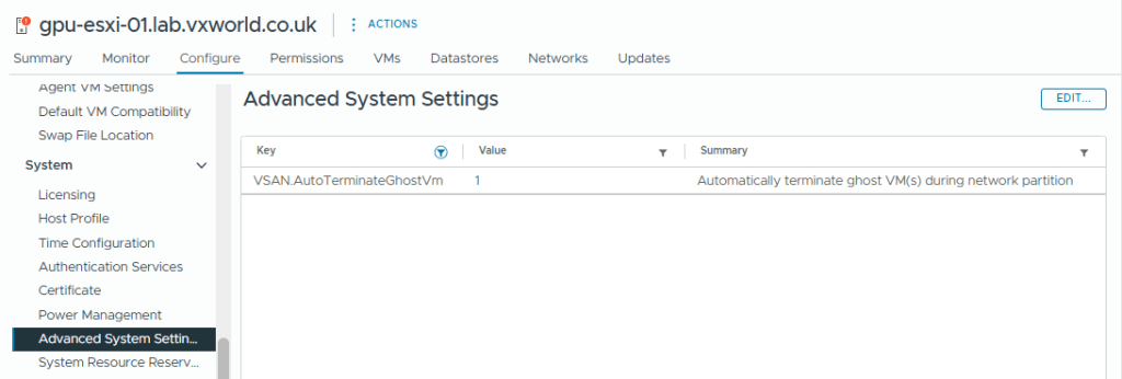
The vSAN setting that will terminate ‘ghosted’ VMs running on an partitioned vSAN node is VSAN.AutoTerminateGhostVm. This was enabled by default on my host but you can check it by selecting the Host -> Configure -> System -> Advanced System Settings and filtering for VSAN.AutoTerminateGhostVm and it should be set to 1. If you want to know more, check out How HA handles a VSAN Stretched Cluster Site Partition
Licencing
The final part of this post is to licence our ESXi Hosts, vCenter and vSAN.
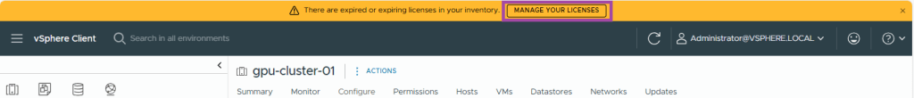
- Click Manage You Licences from the top banner (alternatively, can click the hamburger menu button -> Administration -> Licencing)
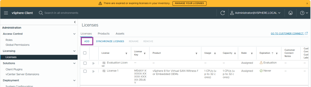
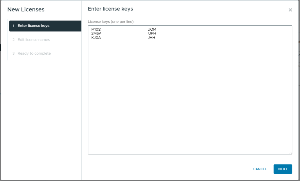
- Under Licenses, click Add
- Enter your licence keys, in my example, I need to enter keys for the following
- VMware vCenter Server 8
- VMware vSAN 8
- VMware vSphere 8 (ESXi)
- Click Next
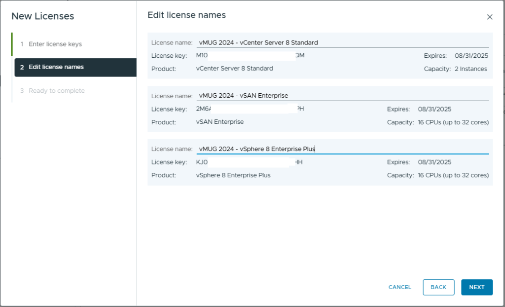
- Optionally, add a Licence Name for each of the imported keys
- Click Next
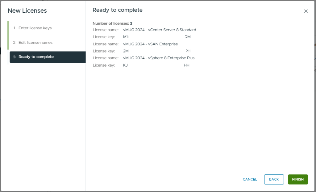
- Review and click Finish
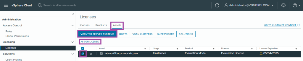
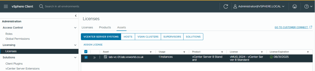
- Now we need to assign the licenses. Browses to the Assets tab
- Click vCenter Server Systems
- Select your vCenter instance
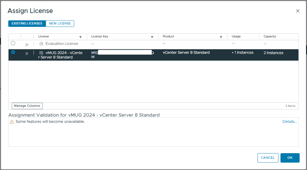
- Click Assign Licence
- Select the correct licence
- Click OK
- You should now see the vCenter showing as licenced
- Select the Hosts tabs
- Select your ESXi Hosts
- Click Assign Licence
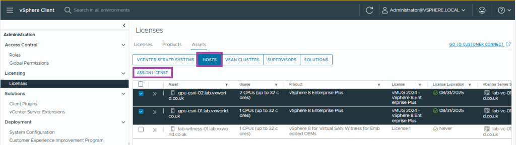
- Select the correct licence and click OK
- Last we need to repeat the process for vSAN
- Select the vSAN Cluster tab
- Select your vSAN Cluster
- Click Assign Licence
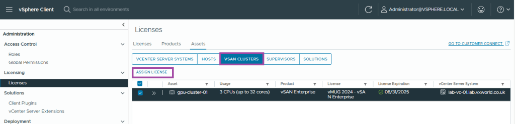
- Select the correct licence and click OK
- Refresh your browser, the license about to expire warning should have gone
Summary
Well done for getting to the end of that one, we covered a lot of ground!
In this post, we’ve walked through the key steps to configure a two-node vSAN ESA stretched cluster. We started by setting up networking with a Virtual Distributed Switch (vDS), adding the second host to the cluster, and integrating the vSAN Witness with vCenter. We then created the cluster and resolved any alerts before moving on to configure vLCM for images, patching, and remediation. The post also covered post-cluster configurations, including setting up Distributed Resource Scheduler (DRS), High Availability (HA), and installing licenses.
Now, it’s time to take it to the next level by adding GPU capabilities! Check out my next post, VMware GPU Homelab: Part 8 – Introduction into NVIDIA vGPU


Leave a reply to Jelle Cancel reply